Cla-val, M+ meter 12 to 35 vdc – Cla-Val 131-01/631-01 User Manual
Page 30
CLA-VAL
Copyright Cla-Val 2011 Printed in USA Specifications subject to change without notice.
P.O. Box 1325
• Newport Beach, CA 92659-0325 • Phone: 949-722-4800 • Fax: 949-548-5441 • E-mail: [email protected] • Website cla-val.com
©
N-X117D (R-3/2011)
Refer to calibration equipment and adjust transmitter potentiometer
marked “NULL” until the meter reads 4 mA. A clockwise turn
increases output. Use care in adjusting the potentiometer while
turning the screwdriver.
5. For the most accurate calibration it is necessary to open valve
fully. CAUTION: This will either allow a high flow rate through the
valve, or the downstream pressure will quickly increase to the
inlet pressure. In some cases, this can be very harmful. Where
this is the case, and there are no block valves in the system to
protect the downstream piping, it should be realized that steps
should be taken to remedy this situation before proceeding further.
Normally, block valves are to be used to protect downstream piping
while the valve is in the open position. Close downstream block
valve. Vent cover chamber to atmosphere. Slightly open inlet
block valve. Allow valve to open while fluid is vented from cover
chamber. When flow stops valve is in the fully open position.
Note: continuous leakage from cover chamber could mean additional
troubleshooting of the main valve or pilot system must be done.
6. With valve in fully open position, inspect position of wire rope
and nut coupler. (See Step 3). Adjust if necessary.
Refer to calibration equipment (see Step 4) and adjust potentiometer
marked “SPAN” until the meter reads 20 mA. A clockwise turn
increases output. Use care in adjusting the potentiometer while
turning the screwdriver.
7. There is some interplay between:
1.) the “span” and “null” settings,
2.) the 4 to 20 mA signal and,
3.) the actual valve open and closed positions.
Repeat steps 4-6 above. Cycle valve from open to closed posi-
tions and check settings as necessary to achieve desired valve
position signal accuracy.
8. Remove all calibration equipment and attach permanent
wiring. Recheck wiring and output signals at remote location. See
Wiring section. Reinstall two cover screws on housing. Recheck
and tighten all fasteners. Bleed air from main valve cover through
small bleed screw and washer located on one wrench flat of
adapter.
MAINTENANCE
The X117D is constructed of durable materials which normally
requiring no lubrication or periodic maintenance. The two ‘O’ rings
(2) (p/n 00951E) in the adapter (5) that seal against the stainless
steel actuating stem (1) will need replacement if signs of leakage
at the stem occur.
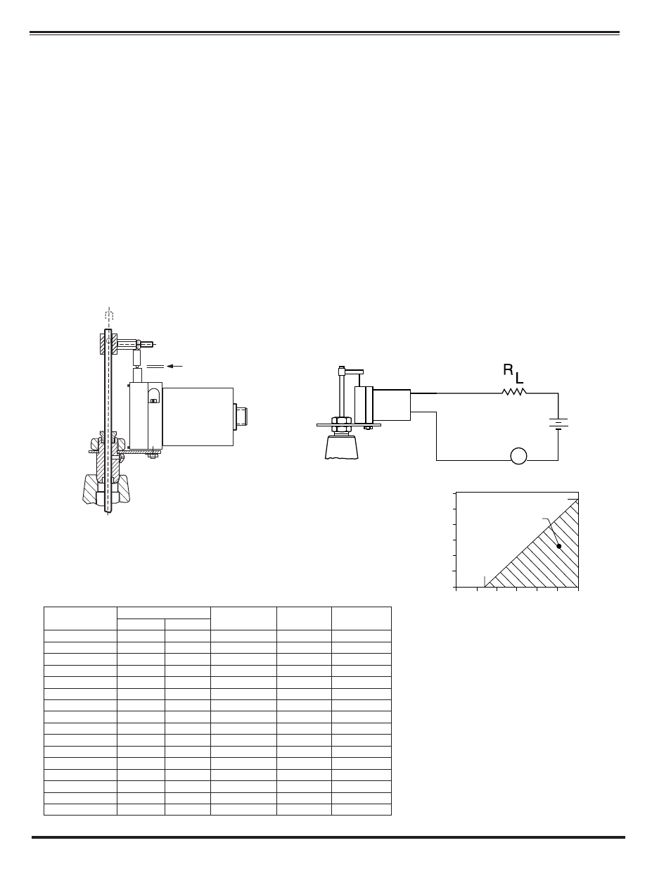
M
+
Meter
12 to
35 VDC
—
+
Red
Black
_
GAP
Coupler gap is set with valve in fully closed position. This establishes the minimum
mechanical position for 4 mA output.
0
10
15
20
35
30
25
0
200
400
800
600
1000
1200
OPERATING ZONE
1150 OHMS
12V
SUPPLY VOLTAGE, V
MAX. LOAD, R (OHMS)
ADJUSTMENT: Zero and span adjustments allow setting the 4 mA position (valve
closed) within 0% to 30% of total transmitter range and setting the 20 mA position
(valve fully open) within 80% to 100% of total transmitter range.
X117D
Part Number
Valve Size (inch)
Valve
Stem Travel
Coupier
Setting
Transmitter
Total Range
100-01
100-20
20000019F
1 1/4
0.400
3/16"
1"
20000019F
1 1/2
0.490
3/16"
1"
20000020A
2
3
0.590
1/8"
1"
20000020A
2 1/2
0.714
1/16"
1"
20000021A
3
0.835
1/16"
1"
20000001A
4
6
1.109
9/16"
2"
20000002A
6
8
1.584
3/16"
2"
20000003A
8
10
2.242
7/16"
3"
20000004A
10
12
2.711
1/8"
3"
20000005A
12
16
3.343
5/16"
4"
20000006A
14
N/A
3.920
9/16"
5"
20000007K
16
20 & 24
4.584
3/16"
5"
20000008J
20
N/A
5.630
2 1/4"
10"
20000008J
24
N/A
6.504
2 1/4"
10"
20000032J
30
N/A
7.500
1 1/2"
10"
20000032J
36
N/A
8.500
1"
10"
“GAP”
Nominal
Minimum