Cla-Val 124-01/624-01 Quick Manual User Manual
Float valve, Model installation / operation / maintenance
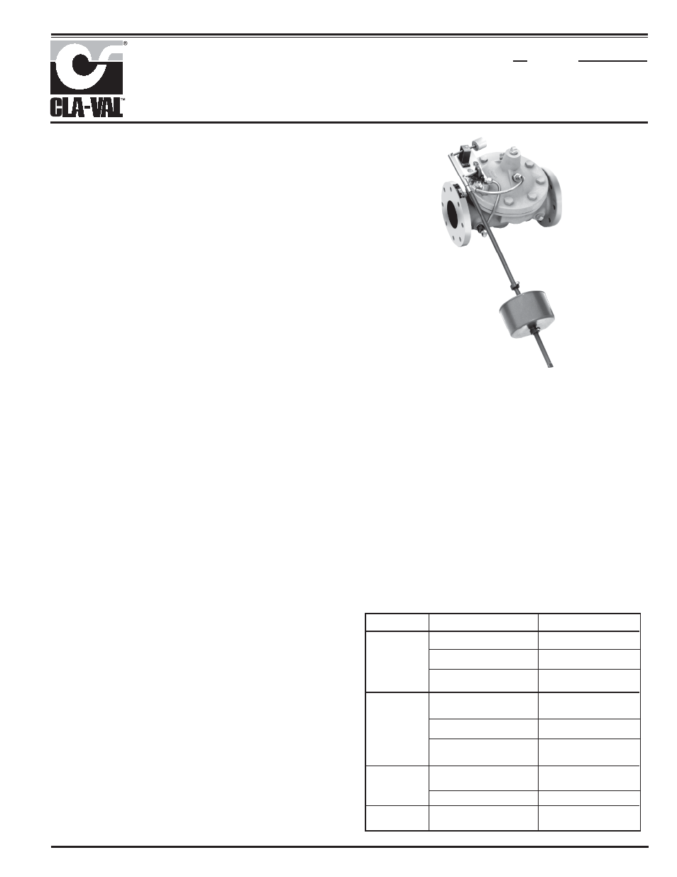
Float Valve
Description
The Cla-Val 124-01/624-01 is an automatic valve designed to open wide
when liquid level reaches a predetermined low point and to shut drip tight
when a predetermined high point is reached. It is a hydraulically operated,
pilot controlled valve. The Pilot Valve is actuated by a float ball to limit the
high and low liquid levels in the tank or reservoir by closing or opening the
main valve. High and low liquid levels are adjustable. The float control can
be remotely located only if the flowing line pressure at the valve inlet (in
psi) is equal to or greater than the elevation (in feet) from the main valve
to the float pilot control.
Installation
1. Allow sufficient room around the valve assembly for adjustments and
maintenance.
NOTE: BEFORE VALVE IS INSTALLED, THE PIPELINE SHOULD BE
FLUSHED OF ALL CHIPS, SCALE AND FOREIGN MATTER.
2. It is recommended that a gate or line block valve be installed upstream
of the 124-01/624-01 Float Valve to facilitate isolating the valve for mainte-
nance. If the discharge from the Float Valve is to atmosphere, an outlet
shutoff valve may not be required.
3. Place the 124-01/624-01 Float Valve in the line with flow through the
valve in the direction of flow arrows or by the inlet nameplate. Check all
fittings and hardware for proper makeup or apparent damage. Be sure
main valve cover bolts or cap screws are tight.
4. Cla-Val Valves operate with maximum efficiency when mounted in horizontal
piping with with the cover UP; however, other positions are acceptable.
Installation with the cover up is advisable to make internal parts readily
accessible for periodic inspection.
5
.
Caution must be taken in the installation of this valve to insure that
galvanic and/or electrolytic action does not take place. The proper use
of dielectric fittings and gaskets are required in all systems using dis-
similar metals.
6. When the valve is installed over water in the tank or reservoir mount the
valve to position the float rod and ball assembly (CF1-C1 item 3 ) vertically down
from the valve.
7. If the surface of the water in the tank is subject to waves by wind or by
valve discharge, a stilling well must be installed around the float ball
assembly. 8'' I.D. PVC pipe is suggested.
8. INITIAL ADJUSTMENT. See CF1-C1 on reverse side for proper assembly
of the float rod, ball and stop collars and threading into the Link Assembly.
Temporarily remove float. Adjust counterweight on the rod to balance the
weight of the link assembly and float rod assembly, less the float. Replace
float.
9. Move float rod to the "up" position. Adjust the upper stop collar on the
float rod assembly approximately three inches above the high water level
desired in the tank. Move float rod to “down” position. Adjust the lower stop
collar on the float rod assembly approximately three inches below the desired
low water level. Tighten stop collar screws on the CF1-C1.
124-01
624-01
Operation and Start-up
1. Prior to pressuring the valve assembly make sure the necessary
gauges to measure pressure in the system are installed as required by
the system engineer. A Cla-Val X101 Valve Position Indicator may be
installed in the center cover port to provide visual indication of the
valve stem during start-up.
CAUTION: During start-up and test procedures a large volume of water
may be discharged downstream. Check that the downstream venting is ade-
quate to prevent damage to personnel and equipment.
2. If the Pilot System shutoff valves (B) are installed, open valves.
(see schematic).
3. Very slowly open the upstream block valve.
4. While the tank is filling, the float rod and link assembly (CF1-C1 item 19)
can be moved slowly to the up position to manually close the main valve.
This operation tests the closure of the Float Valve and also will purge air
SYMPTOM
PROBABLE CAUSE
REMEDY
Continuous flow
Damaged valve diaphragm
Replace diaphragm
from float pilot
system discharge
port
Loose main valve (1) stem nut
Tighten stem nut
Damaged float pilot control (2)
Replace pilot valve
assembly (See P-CFI-CI)
Main Valve fails
Too low pressure differential
Restrict valve opening with
to close
across valve (Need 5 psi d Min
Cla-Val X102A flow limiting
under flowing conditions)
assembly (Contact Cla-Val)
Isolation valve in control tubing
Open isolation valve. clean
closed or clogged X46 strainer
strainer
Float and float rod fails to move
Free float mechanism
with liquid level change (stays in
down position)
Main Valve
Float and float rod fails to move
Free float mechanism
fails to open
with liquid level change (stays in
up position)
Inlet gate or block valve closed
Open valve
Main Valve
Air in cover
Bleed all air with float
Vibrates when
in the up position
closing
from the control lines and cover chamber. Carefully loosen tube fittings at
highest points and bleed air from system. Carefully loosen the plug at
top of main valve cover. If an indicator is installed, carefully loosen the
vent at top of indicator. If the valve is installed on its side loosen the
top 4 cover bolts to bleed air trapped in the cover. Bleed air from cover
and tighten plug. Tighten tube fittings.
Maintenance
1. Cla-Val Valves and Controls require no lubrication or packing and a
minimum of maintenance. However, a periodic inspection schedule
should be established to determine how the fluid handled is affecting the
efficiency of the valve assembly. Minimum of once per year.
2. Repair and maintenance procedures of the Cla-Val Hytrol main Valve
and the control components are included in a more detailed IOM manu-
al. It can be downloaded from our web site (www.cla-val.com) or obtained
by contacting a Cla-Val Regional Sales Office.
3. When ordering parts always refer to the catalog number and stock
number on the valve nameplate.
MODEL
INSTALLATION / OPERATION / MAINTENANCE