Cla-val, Model 90-99 dimensions, Pilot system specifications – Cla-Val 90-99 User Manual
Page 2: Materials, Pressure ratings
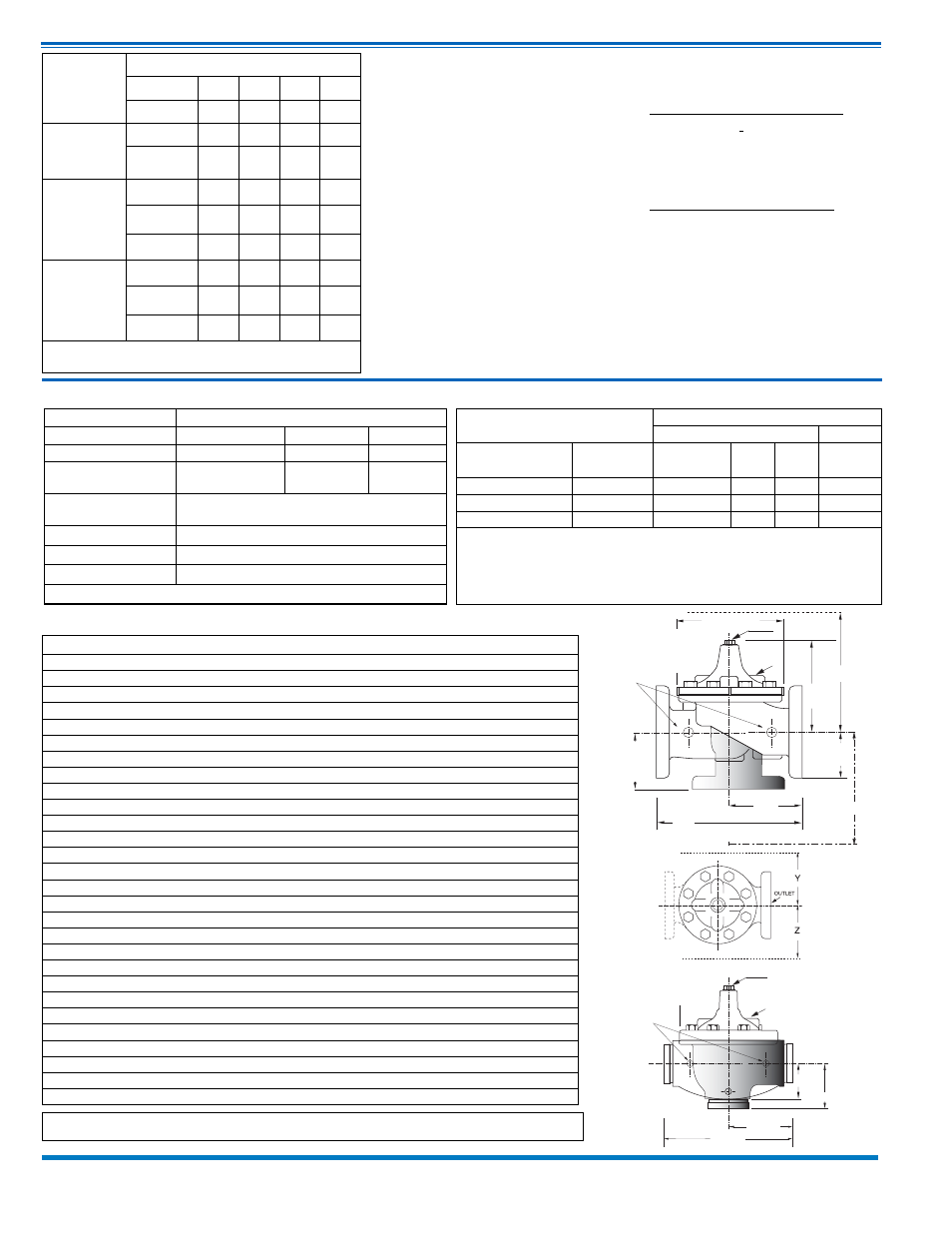
Model 90-99 Dimensions
(In Inches)
Materials
Standard Pilot System Materials
Pilot Control: Bronze ASTM B62
Trim: Stainless Steel Type 303
Rubber: Buna-N
®
Synthetic
Rubber
Optional Pilot System Materials
Pilot Systems are available with
optional Aluminum, Stainless Steel or
Monel materials.
Note: Available with remote sensing control
Pilot System Specifications
Adjustment Ranges
CRD
2 to
30 psi
15 to
75 psi
20 to 105 psi
30 to 300 psi*
*Supplied unless otherwise specified
Other ranges available, please consult
factory.
Temperature Range: Water: 180°
CLA-VAL
Copyright Cla-Val 2012 Printed in USA Specifications subject to change without notice.
P.O. Box 1325
• Newport Beach, CA 92659-0325 • Phone: 949-722-4800 • Fax: 949-548-5441 • E-mail: [email protected] • Website cla-val.com
©
E-90-99 (R-01/2012)
100-01 Series is the full internal port Hytrol
For 100-01 basic valves • Suggested flow calculations are based on flow through Schedule 40 Pipe.
• Max continuous flow is approx. 20 ft/sec (6.1 meters/sec).
• Max intermittent is approx. 25 ft/sec (7.6 meters/sec).
Materials
Valve Body & Cover
Pressure Class
Flanged
Threaded
Grade
Material
ANSI
Standards*
150
Class
300
Class
End‡
Details
ASTM A536
Ductile Iron
B16.42
250
400
400
ASTM A216-WCB
Cast Steel
B16.5
285
400
400
ASTM B62
Bronze
B16.24
225
400
400
Note:
* ANSI standards are for flange dimensions only.
Flanged valves are available faced but not drilled.
‡ End Details machined to ANSI B2.1 specifications.
Valves for higher pressure are available; consult factory for details
Pressure Ratings
(Recommended Maximum Pressure - psi)
G
GG
GGG
D
Inlet
DD
DDD
F
FF
X
100-01
Threaded &
Flanged
A
C
(MAX)
K
J
H
Inlet
Outlet
AA
AAA
B
(Diameter)
W
GGGG
DDDD
Inlet
AAAA
EE
K
J
H
Inlet
Outlet
Low Flow
By-Pass Valve
100-01 Grooved
Valve Size (Inches)
4
6
8
10
A Threaded
—
—
—
—
AA 150 ANSI
15.00
20.00
25.38
29.75
AAA 300 ANSI
15.62
21.00
26.38
31.12
AAAA Grooved End
15.00
20.00
25.38
—
B Dia.
11.50
15.75
20.00
23.62
C Max.
10.62
13.38
16.00
17.12
CC Max. Grooved End
9.31
12.12
14.62
—
D Threaded
—
—
—
—
DD 150 ANSI
7.50
10.00
12.69
14.88
DDD 300 ANSI
7.88
10.50
13.25
15.56
DDDD Grooved End
7.50
—
—
—
E
—
—
—
—
EE Grooved End
4.25
6.00
7.56
—
F 150 ANSI
4.50
5.50
6.75
8.00
FF 300 ANSI
5.00
6.25
7.50
8.75
G Threaded
—
—
—
—
GG 150 ANSI
5.00
6.00
8.00
8.62
GGG 300 ANSI
5.31
6.50
8.50
9.31
GGGG Grooved End
5.00
—
—
—
H NPT Body Tapping
.75
.75
1
1
J NPT Cover
Center Plug
.75
.75
1
1
K NPT Cover Tapping
.75
.75
1
1
Stem Travel
1.1
1.7
2.3
2.8
Approx. Ship Wt. Lbs.
140
285
500
780
X Pilot System
17
29
31
33
Y Pilot System
12
20
22
24
Z Pilot System
12
20
22
24
W Pilot System
34
34
36
38
*Globe Grooved Only
Component
Standard Material Combinations
Body & Cover
Ductile Iron Epoxy
Cast Steel
Bronze
Available Sizes
4" - 10"
4" - 10"
4" - 10"
Disc Retainer &
Diaphragm Washer
Cast Iron
Cast Steel
Bronze
Trim: Disc Guide,
Seat & Cover Bearing
Bronze is Standard
Stainless Steel is Optional
Disc
Buna-N
®
Rubber
Diaphragm
Nylon Reinforced Buna-N
®
Rubber
Stem, Nut & Spring
Stainless Steel
For material options not listed, consult factory.
Many factors should be considered in sizing pressure reducing valves, including inlet pressure, outlet pressure
and flow rates. For sizing questions or cavitation analysis, consult Cla-Val with system details.
90-99
Valve
Selection
100-01 Pattern:
Globe (G), Angle (A),
End Connections:
Threaded (T), Grooved (GR), Flanged (F) Sizes
Inches
4
6
8
10
mm
100
150
200
250
Basic Valve
100-01
Pattern
G, A G, A G, A G, A
End Detail
F,
Gr
F,
Gr*
F,
Gr*
F
Suggested
Flow
(gpm)
Maximum
800
1800
3100
4900
Maximum
Intermittent
990
2250
3900
6150
Minimum
1
1
1
1
Suggested
Flow
(Liters/Sec)
Maximum
50
113
195
309
Maximum
Intermittent
62
142
246
387
Minimum
0.06
0.06
0.06
0.06
100-01 Series is the full internal port Hytrol.
For Lower Flows Consult Factory *Globe Grooved Only