Cla-val – Cla-Val 33A User Manual
Page 2
CLA-VAL
Copyright Cla-Val 2010 Printed in USA Specifications subject to change without notice.
P.O. Box 1325
• Newport Beach, CA 92659-0325 • Phone: 949-722-4800 • Fax: 949-548-5441 • E-mail: [email protected] • Website cla-val.com
©
N-33A (R-10/2010)
PROBLEMS / SOLUTIONS
1. Leakage at Inlet Connection:
Tighten valve threaded connection. If leaks persist, remove
valve and seals threads with pipe sealant or tape.
2. Leakage at Cover/Body joint:
Tighten bolts per Table 2, replace gasket.
3. Small or Large Orifice Leakage:
Flush valve to remove debris. Disassemble and inspect both
seat, orifices and float for wear or damage. Replace as needed
with a float kit or seat kit
4. Small Orifice not Releasing Air Under Pressure:
Check that operating pressure does not exceed Working
Pressure on nameplate. Perform inspection step 3 and
disassemble valve if problem persists.
DISASSEMBLY
The valve can be disassembled without removing it from the
pipeline, or it may be removed from the line. All work on the
valve should be performed by a skilled mechanic. Special tools
are NOT required.
CAUTION: Drain the vale and de-pressurized before removing
the cover or pressure may causing injury.
1. Close inlet shut-off valve. Slowly open drain valve or remove
drain plug. Remove the covers bolts slowly.
2. Pry cover loose and lift off valve body.
3. Remove entire seat & float assemblies inspect for damage or
wear
4. Clean and inspect parts. Note: Shake float & if water inside
float replace it and worn parts as necessary.
NOTE:
Float Kit & Seat Kit includes cover gasket
REASSEMBLY
1. All parts must be cleaned and gaskets surfaces cleaned
with a stiff wire brush in the direction of the serration or
machine marks. Worn parts, gaskets and seal should be
replaced during reassembly.
2. Apply Loctite or similar Compound to threaded Connections
3. Stand valve body vertically. Insert entire delrin frame, seat &
float assembly into register. Move float up/down to insure
concentricity and no binding.
4. Lay new cover gasket on clean surface and apply a gasket
compound such as Permatex #80065 to both surfaces.
Assemble gasket and cover over bolt holes in body.
5. Insert lubricated bolts and tighten to the torques listed in
Table 2.
6. Place valve back in service. Refer to the installation
instruction. Slowly open inlet isolation valve.
PARTS AND SERVICE
Parts and service are available from your local representative
or the factory. Make note of the valve Model No. and Working
Pressure located on the valve nameplate.
BOLT SIZE
1/4”-20
5/16”-18
3/8”-24
7/16”-32
TORQUE (FT. LBS.)
6
11
19
30
TABLE 2. VALVE COVER BOLT TORQUES
Specifications
Pressure Ratings
Materials
500 psi Ductile Iron
Body and Cover:
Body and Cover
Ductile Iron
ASTM A536 65-45-12
500 psi Stainless Steel
Body and Cover
Body and Cover
Stainless Steel T303
600 psi Cast Steel
Body and Cover
Body and Cover
Cast Steel ASTM A 216 WCB
Note:
Readily available for seawater service and other
corrosive fluids applications Made of:
Monel - Bronze’s - Stainless Steel
Standard Internals
Float: Stainless Steel T304
Balance internals parts Stainless Steel and Delrin
Seals Nitrile Rubber or Viton (extra cost)
Temperature Range
Water to 180° F
Optional:
1. Fusion epoxy lined and coated at extra cost
2. For Well Service Install Throttling Device on the Outlet
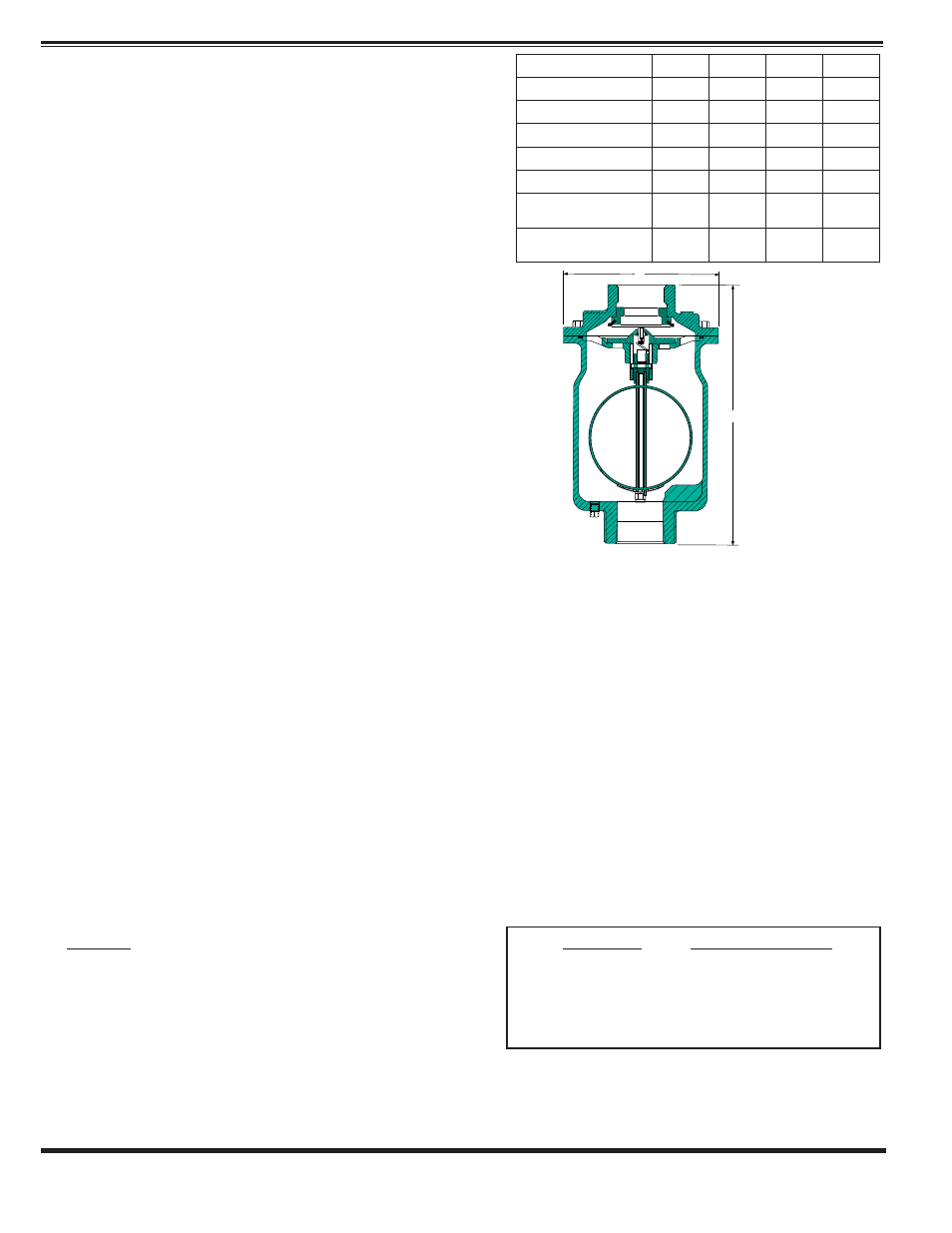
MODEL 33A - 1”,2”,3” and 4” SIZES
Single Body Combination Air Vacuum
Air Release Valve
Valve Size
1"
2"
3"
4"
A
9.10
12.44
12.75
12.75
B
6.25
7.50
9.00
9.00
Inlet (NPT)
1" NPT 2" NPT 3" NPT 4" NPT
Outlet (NPT)
1" NPT 2" NPT 4" NPT 4" NPT
Shipping Wt. (Lbs.)*
25
29
38
40
Max. Operating PSI
(Std. Orifice)
300
500
300
300
Max. Operating PSI
(with .076 Orifice)
300
500
450
450
*
Approximate
B
A
OUTLET
INLET
Available Flanged