Installation/operation, Setting the breaker valve, Sewage applications – Cla-Val 38VB/AR Series User Manual
Page 3: Flushing procedure fig. 4
INSTALLATION/OPERATION
Installation of the vacuum breaker valve is important for
its proper operation. Valves must be installed in a vertical
position with the inlet down on high points of a pipeline or
tank, where vacuum conditions are anticipated. A full
ported shut-off valve, under the valve, should be installed
for future inspection or maintenance.
The vacuum breaker valve will open to allow air to re-
enter the pipeline or tank for any reason that the pipeline
or tank is drained. Allowing air re-entry will prevent vacu-
um forming that would otherwise cause pipeline or
tank to collapse and also prevent water column separa-
tions which can cause pressure surges and damage as
the water column rejoins.
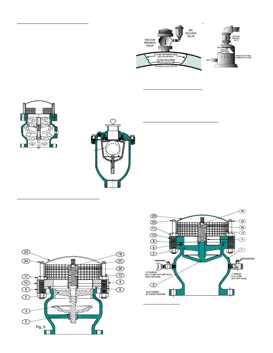
SETTING THE BREAKER VALVE
The standard vacuum breaker Fig.1 and Fig.1A above
are set from the factory to open between 1/4” & 1/2” PSI.
This is setting is not adjustable. The vacuum breaker having
an external spring for water or for sewage is set at the
factory per customers specification. After installation the
Vacuum breaker can be re-adjusted to suit actual operat-
ing conditions simply by tightening or loosening #18 seat
collar Fig 3.
SEWAGE APPLICATIONS
The Cla-Val Vacuum Breaker for sewage has clear flow
unobstructed body to prevent clogging. This valve is supplied
with (2) 1” full flow valves for flushing out the valve
periodically as may be required.
FLUSHING PROCEDURE FIG. 4
1. Shut the isolation valve under the vacuum breaker
(As provided by others).
2. Depressurize the vacuum breaker by slowly opening
one of the full flow valves mounted on the valve body.
3. Flush with pressurized water from a water tanker or
remove the vacuum from the pipeline or tank and take
it to the maintenance shop for cleaning.
4. During flushing, push down the external spring to
create a cleansing action around the plug #3 and thru
the sea. #2.
MAINTENANCE
Cla-Val Vacuum Breakers operate automatically and
no regular lubrication or maintenance is required.
A visual inspection annually to observe if any leakage
is occurring by simply removing the hood #22 will be
more than adequate.
Fig.4
TYPICAL INSTALLATION
VACUUM
BREAKER
LARGER
ORIFICE
STANDARD FLANGE STYLE
SMALL
ORIFICE
AIR RELEASE
OPEN
CLOSED
VACUUM
BREAKER
LARGE
ORIFICE
AIR
OUT
AIR
IN
Large
Orifice
Fig 1A
Fig 1.
STANDARD THREADED STYLE
ADJUSTABLE
Valve Shown in
Open Position
For Sewage