Cla-val, When ordering, please specify, Pilot system specifications – Cla-Val 98-06/698-06 Technical Manual User Manual
Page 8: Schematic diagram, Optional features
2
INLET
B
B
6A
P1
S
C
6B
3
7
1
5
9
ADJUSTMENT
HIGH PRESSURE
10
LOW
ADJUSTMENT
PRESSURE
11
4
B
8
ADJUSTMENT SCREW
P2
Patent
Pending
CLA-VAL
Copyright Cla-Val 2011 Printed in USA Specifications subject to change without notice.
P.O. Box 1325
• Newport Beach, CA 92659-0325 • Phone: 949-722-4800 • Fax: 949-548-5441 • E-mail: [email protected] • Website cla-val.com
©
Outlet Pressure Adjustment Range:
High Flow Pressure Setting:
15-75 psi Maximum
Low Flow Pressure Setting:
Up to 30 psi below high setting
Temperature Range
Water: to 180°F
Materials
Standard Pilot System Materials
Pilot Control: Bronze ASTM B62
Trim: Stainless Steel Type 303
Rubber: Buna-N
®
Synthetic Rubber
When Ordering, Please Specify
1. Catalog No. 98-06 or 698-06
2. Valve Size
3. Pattern - Globe or Angle
4. Pressure Class
5. Threaded or Flanged
6. Trim Material
7. Desired Options
8. When Vertically Installed
Pilot System Specifications
E-98-06 (R-7/2011)
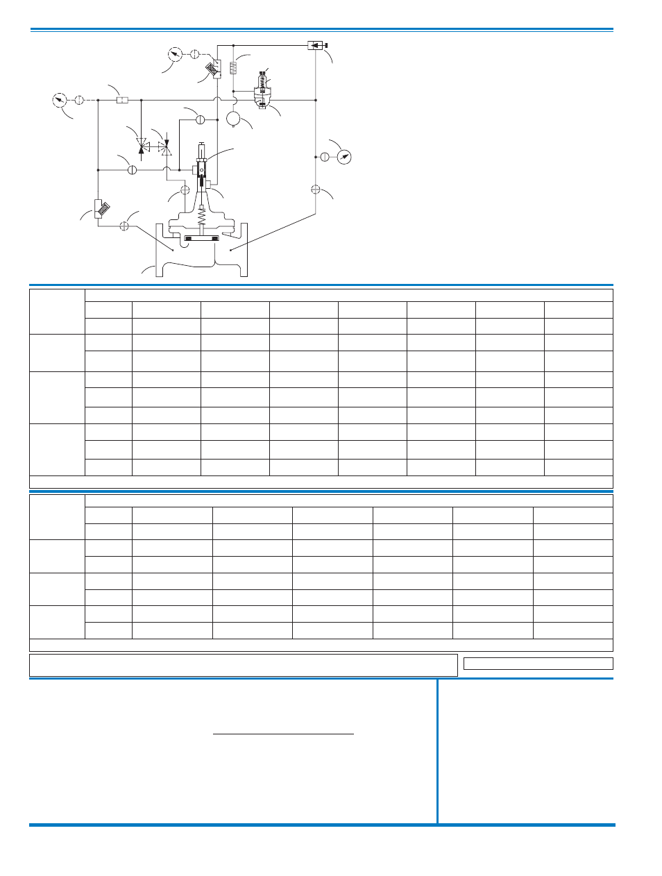
Schematic Diagram
Item Description
1
Hytrol (Main Valve)
2
X43 “Y” Strainer
3
X58C Restriction Assembly
4
CPM-A Pressure Management Control
5
X78-4 Stem Assembly + X101 Valve
Position Indicator Assembly
6
CK2 (Isolation Valve)
7
X44A Strainer Orifice Assembly
8
X141 Gage Assembly
9
6120 Needle Valve
10
X58E Restriction Assembly
11
Accumulator (Air Charged)
Optional Features
Item Description
B
CK2 (Isolation Valve)
C
CV Flow Control (Closing)
P
X141 Gage Assembly
S
CV Flow Control (Opening)
Many factors should be considered in sizing pressure reducing valves including inlet pressure, outlet pressure and flow rates.
For sizing questions or cavitation analysis, consult Cla-Val with system details.
Not Recommended for Dead-end Service
98-06/698-06
SCHEMATIC
98-06
Valve
Selection
100-01 Pattern: Globe (G), Angle (A), End Connections: Threaded (T), Grooved (GR), Flanged (F) Indicate Available Sizes
Inches
2
2
1
⁄
2
3
4
6
8
10
mm
50
65
80
100
150
200
250
Basic Valve
100-01
Pattern
G, A
G, A
G, A
G, A
G, A
G, A
G, A
End Detail
T, F,
Gr
T, F,
Gr*
T, F,
Gr
F,
Gr
F,
Gr*
F,
Gr*
F
Suggested
Flow
(gpm)
Maximum
210
300
460
800
1800
3100
4900
Maximum
Intermittent
260
370
580
990
2250
3900
6150
Minimum
1
2
2
4
10
15
35
Suggested
Flow
(Liters/Sec)
Maximum
13
19
29
50
113
195
309
Maximum
Intermittent
16
23
37
62
142
246
387
Minimum
.06
.09
0.13
0.25
0.63
0.95
2.2
100-01 Series is the full internal port Hytrol.
For Lower Flows Consult Factory
*
Globe Grooved Only
698-06
Valve
Selection
100-20 Pattern: Globe (G), Angle (A), End Connections: Flanged (F) Indicate Available Sizes
Inches
3
4
6
8
10
12
mm
80
100
150
200
250
300
Basic Valve
100-20
Pattern
G
G, A
G, A
G, A
G
G
End Detail
F
F
F
F
F
F
Suggested
Flow
(gpm)
Maximum
260
580
1025
2300
4100
6400
Minimum
1
2
4
10
15
35
Suggested
Flow
(Liters/Sec)
Maximum
16
37
65
145
258
403
Minimum
.06
.13
.25
.63
.95
2.2
100-20 Series is the reduced internal port size version of the 100-01 Series.
For Lower Flows Consult Factory