Cla-val – Cla-Val 582SWS Series User Manual
Page 4
Page 4
CLA-VAL
© 2004 Cla-Val Printed in USA Specifications subject to change without notice.
P.O. Box 1325
• Newport Beach, CA 92659-0325 • Phone: 949-722-4800 • Fax: 949-548-5441 • E-mail: [email protected] • Website cla-val.com
N-582 Series
2
5
4
10
1
FLOW
2
5
FLOW
4
1
8
9
ANSI CLASS 125
BOL
T
CIRCLE
7
3A
3B
4B
6A
6B
10
DETAIL
DESCRIPTION
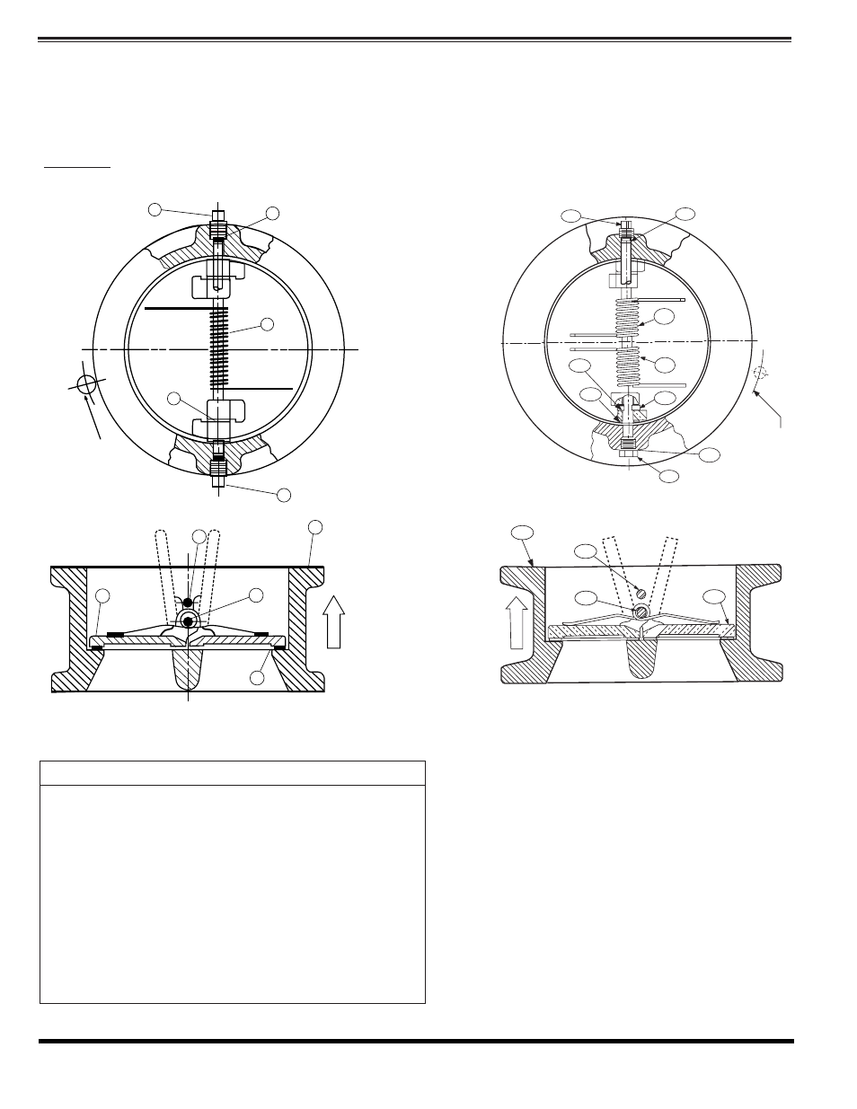
Table 6A Check Valve Parts List
Sizes 18” & Larger Utilizes (2) Springs
Figure 7 Two Door Check Valve
Figure 6 Two Door Check Valve
MATERIAL
1
2
3, 3A, 3B
4
4A
4B
5
6
6A
6B
7
8
9
10
Body
Cast Iron
Doors
Bronze
Spring*
(qty 2springs on 18” and larger)
Stainless Steel
Hinge Pin
Stainless Steel
Hinge Pin
Stainless Steel
Shaft collar
(item 4B on 36” and larger sizes only)
Stainless Steel
Stop Pin
Stainless Steel
Bearing* (qty. 4)
Stainless Steel
Inner Bearing*
Stainless Steel
Outer Bearing*
Stainless Steel
Hinge Pin Retainer*
Steel
Stop Pin Retainer*
Steel
Stabilizer Spheres*
Buna-N
®
O-Ring*
Buna-N
®
(18” & Larger)
*Recommended Spare Parts
PARTS AND SERVICE:
Parts and service are available from your local
representative or the factory. Make note of the
Valve Size and Model No. located on the valve
nameplate.
Contact Your Local Cla-Val
Representative or Distributor
A sales representative will quote prices for
parts or arrange for service as needed
Valve Construction (14” - 60”)
The standard check valve body general details of construction are illustrated in Figure 6, 7, 8 tables
The body (1) is either wafer style to fit between two pipe flanges or lug style for bolting two pipes flanges. The resilient seat is bonded
to the body and not adjustable or replaceable in the field.
The doors (2) and Torsion spring (3) are the only moving parts and require no maintenance or lubrication
Warning: Removal of mating flanges with out draining the pipeline may cause injury or damage to the valve
8
ANSI CLASS
125, 150,
BOLT CIRCLE
9
7
6
3