Cla-val, Pilot system specifications, Model 81-01 dimensions – Cla-Val 81-12 User Manual
Page 2: Pressure ratings, Materials
Temperature Rating
Water: to 180°F. Max.
Speed Controls
For valves with opening and closing
speed controls order Model 81-02
Materials
Standard Pilot System Materials
Fittings:
Brass
Tubing: Copper
Optional Pilot System Materials
Pilot Systems are available
with optional stainless steel
or Monel materials.
Pilot System Specifications
1. Catalog No. 81-12
2. Valve Size
3. Pattern: Globe
or Angle
4. Pressure Class
5. Threaded or
Flanged
6. Desired Options
7. When Vertically
Installed
When ordering
please specify:
E-81-12 (R-5/2013)
CLA-VAL
Copyright Cla-Val 2013 Printed in USA Specifications subject to change without notice.
P.O. Box 1325
• Newport Beach, CA 92659-0325 • Phone: 949-722-4800 • Fax: 949-548-5441 • E-mail: [email protected] • Website cla-val.com
©
81-12
Valve
Selection
100-01 Pattern:
Globe (G), Angle (A),
End Connections:
Threaded (T),
Grooved (GR), Flanged (F) Indicate Available Sizes
Inches
1
1¼
1½
2
2½
3
4
mm
25
32
40
50
65
80
100
Basic Valve
100-01
Pattern
G, A
G, A
G, A
G, A
G, A
G, A
G, A
End
Detail
T
T
T, F,
GR
T, F,
GR
T, F,
GR*
T, F,
GR
T, F,
GR
Suggested
Flow
(gpm)
Maximum
55
93
125
210
300
460
240
Suggested
Flow
(Liters/Sec)
Maximum
3.5
6
8
13
19
29
15.1
100-01 Series is the full internal port Hytrol.
*
Globe Grooved Only
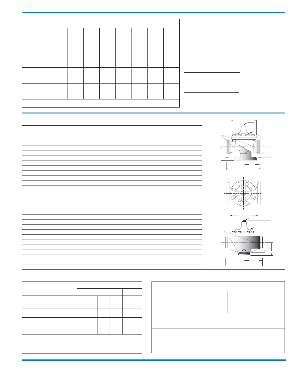
Model 81-01 Dimensions
(In Inches)
Valve Size (Inches)
1
1¼
1½
2
2½
3
4
A Threaded
7.25
7.25
7.25
9.38
11.00
12.50
—
AA 150 ANSI
—
—
8.50
9.38
11.00
12.00
15.00
AAA 300 ANSI
—
—
9.00
10.00
11.62
13.25
15.62
AAAA Grooved End
—
—
8.50
9.00
11.00
12.50
15.00
B Dia.
5.62
5.62
5.62
6.62
8.00
9.12
11.50
C Max.
5.50
5.50
5.50
6.50
7.56
8.19
10.62
CC Max. Grooved End
—
—
4.75
5.75
6.88
7.25
9.31
D Threaded
3.25
3.25
3.25
4.75
5.50
6.00
—
DD 150 ANSI
—
—
4.00
4.75
5.50
6.00
7.50
DDD 300 ANSI
—
—
4.25
5.00
5.88
6.38
7.88
DDDD Grooved End
—
—
—
4.75
—
6.00
7.50
E
1.12
1.12
1.12
1.50
2.69
2.06
3.19
EE Grooved End
—
—
2.00
2.50
2.88
3.12
4.25
F 150 ANSI
—
—
2.50
3.00
3.50
3.75
4.50
FF 300 ANSI
—
—
3.06
3.25
3.75
4.13
5.00
G Threaded
1.88
1.88
1.88
3.25
4.00
4.50
—
GG 150 ANSI
—
—
4.00
3.25
4.00
4.00
5.00
GGG 300 ANSI
—
—
4.25
3.50
4.31
4.38
5.31
GGGG Grooved End
—
—
—
3.25
—
4.25
5.00
H NPT Body Tapping
0.375
0.375
0.375
0.375
0.50
0.50
0.75
J NPT Cover Center Plug
0.25
0.25
0.25
0.50
0.50
0.50
0.75
K NPT Cover Tapping
0.375
0.375
0.375
0.375
0.50
0.50
0.75
Stem Travel
0.40
0.40
0.40
0.60
0.70
0.80
1.10
Approx. Ship Wt. Lbs.
15.00
15.00
15.00
35.00
50.00
70.00
140.00
X Pilot System
11.00
11.00
11.00
13.00
14.00
15.00
17.00
Y Pilot System
9.00
9.00
9.00
9.00
10.00
11.00
12.00
Z Pilot System
9.00
9.00
9.00
9.00
10.00
11.00
12.00
Component
Standard Material Combinations
Body & Cover
Ductile Iron
Cast Steel
Bronze
Available Sizes
1" - 4"
1" - 4"
1" - 4"
Disc Retainer &
Diaphragm Washer
Cast Iron
Cast Steel
Bronze
Trim: Disc Guide,
Seat & Cover Bearing
Bronze is Standard
Stainless Steel is Optional
Disc
Buna-N
®
Rubber
Diaphragm
Nylon Reinforced Buna-N
®
Rubber
Stem, Nut & Spring
Stainless Steel
For material options not listed, consult factory.
Cla-Val manufactures valves in more than 50 different alloys.
Valve Body & Cover
Pressure Class
Flanged
Threaded
Grade
Material
ANSI
Standards*
150
Class
300
Class
300
Class
ASTM A536
Ductile Iron B16.42
250
400
400
ASTM A216-WCB
Cast Steel
B16.5
285
400
400
ASTM B62
Bronze
B16.24
225
400
400
Note: * ANSI standards are for flange dimensions only.
Flanged valves are available faced but not drilled.
‡ End Details machined to ANSI B2.1 specifications.
Valves for higher pressure are available; consult factory for details
Pressure Ratings
(Recommended Maximum Pressure - psi)
Materials
G
GG
GGG
D
Inlet
DD
DDD
F
FF
100-01
Threaded &
Flanged
A
E
C
(MAX)
K
J
H
Inlet
Outlet
AA
AAA
B
(Diameter)
GGGG
DDDD
Inlet
AAAA
100-01
Grooved
EE
CC
(MAX)
K
J
H
Inlet
Outlet
B
(Diameter)