Cla-val, Dimensions – Cla-Val 501A Series User Manual
Page 2
For a more detailed IOM Manual go to www.cla-val.com or contact a Cla-Val Regional Sales Office.
CLA-VAL
Copyright Cla-Val 2011 Printed in USA Specifications subject to change without notice.
P.O. Box 1325
• Newport Beach, CA 92659-0325 • Phone: 949-722-4800 • Fax: 949-548-5441 • E-mail: [email protected] • Website cla-val.com
©
N-501A
3. Lay valve body down with seat and hinge arm cavity facing
upwards. Use care to prevent damage.
4. Replace two bushings in valve body after using a very small
amount of waterproof grease on the inside of the bushings.
5. Install new 'O' ring seat seal in dovetail groove in valve body.
The groove is slightly larger in diameter than the 'O' ring to secure
'O' ring in place. Lubricate the 'O' ring with a very small amount of
waterproof grease before installing. Stretch 'O' ring and place or
"pop" it into groove at two opposite locations. Then push remain-
der of 'O' ring into the groove by hand pressure making sure that it
is in flat and not twisted.
6. Carefully place clapper and hinge arm assembly into body with
seating surfaces together. Line up hinge arm holes, bushings, and
hinge arm cavity of body.
7. Lubricate hinge pin with a very small amount of waterproof
grease and reinstall (using threaded rod tool) from the outside
through body, first bushing, and part of hinge arm.
8. Carefully compress torsion spring slightly and place in center of
hinge arm cavity. Insert hinge pin through spring, remaining part of
hinge arm, and second bushing. Be sure that threaded end of
hinge pin can be seen from the outside of the valve body.
9. Replace plug.
10. Check valve for freedom of movement. Place valve in a verti-
cal position with hinge pin at top. Move clapper assembly by hand
through full stroke. Larger valves should be supported to prevent
valve overturning and causing damage.
11. Conduct leak test if possible.
12. Reinstall valve in pipeline
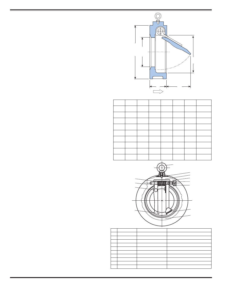
Series 501A - Wafer Swing Check Valves
(Standard) 2" - 12"
Technical Data
Pressure Rating:
235 Max psi
Temperature Range:-
5º to 210º F
Disc Cracking Pressure: All Valves equal
approximately 0.5 psi
Fluids:
Water, Wastewater, Chemicals and
Petroleum
Dimensions
(In Inches)
Size
A
B
C
D
E
(Deg.)
Q
Wt.Lbs.
2
4
1
⁄
8
1
11
⁄
16
1
3
⁄
8
13
⁄
16
59
2
3.1
2
1
⁄
2
4
7
⁄
8
1
13
⁄
16
1
3
⁄
4
1
1
⁄
16
60
2
7
⁄
8
4.2
3
5
3
⁄
8
2
1
⁄
2
2
3
⁄
8
1
1
⁄
8
62
3
6.6
4
6
3
⁄
4
2
1
⁄
2
3
1
⁄
8
1
5
⁄
8
60
4
8.1
5
7
3
⁄
4
2
3
⁄
4
3
7
⁄
8
2
1
⁄
2
61
5
12.3
6
8
3
⁄
4
3
4
1
⁄
2
3
3
⁄
4
72
6
18
8
11
3
1
⁄
2
6
1
⁄
4
4
3
⁄
4
70
7
3
⁄
4
27.3
10
13
3
⁄
8
4
1
⁄
2
7
5
⁄
8
5
3
⁄
4
66
9
3
⁄
4
51.3
12
16
1
⁄
8
4
1
⁄
2
9
1
⁄
2
7
3
⁄
8
65
11
3
⁄
4
72.6
No. Description
Material
Specifications
1
Body
Cast Iron or Steel
ASTM A48 / ASTM A216
2
Disc
316 Stainless Steel ASTM A473 / A743M- CF8M
3
Shaft
316 Stainless Steel ASTM A276
4
Plug
304 Stainless Steel ASTM A276
5
Seat (Shaft) PTFE
-
6
Seat (Body) Nitrile or Viton
TM
Commercial
7
Bushing
316 Stainless Steel ASTM A276
8
Travel Stop 316 Stainless Steel ASTM A276
9
Tag
Aluminum
-
10 Spring
304 Stainless Steel -
10
3
8
2
EyeBolt
11
9
5
7
4
6
1
B
D
C
DIA.
A
DIA.
FLOW
Q