Cla-val – Cla-Val 584 User Manual
Page 2
TROUBLESHOOTING
Several problems and solutions are presented below to assist you in
troubleshooting the valve.
• Leakage at Bottom Actuator: Remove line pressure and
exercise actuator. If leak persists, replace seals in actuator;
see the Return Flow Actuator Seal Replacement Procedure
• Leakage at Cover or Flanges: Tighten bolts, replace cover seal.
• Valve Leaks when Closed: Inspect disc for damage and
replace. Inspect body seating surface and clean if necessary.
• Valve Does not Open: Check for obstruction in valve or
pipeline. Operating pressure may be less than cracking pressure.
If less than 0.5 psig, review application with factory.
DISASSEMBLY
The valve can be disassembled without removing it from the
pipeline. Alternately, for convenience, the valve can be removed
from the line. All work on the valve should be performed by a skilled
mechanic with proper tools and a power hoist for larger valves.
Disassembly may be required to inspect the disc for wear or the
valve for deposits.
WARNING: The line must be drained before removing the cover
or pressure may be released causing bodily harm.
1 Relieve pressure and drain the pipeline.
Remove the cover bolts on the top cover.
2 Carefully pry cover loose and lift off. 12” and larger valves
have tapped holes in cover for lifting eyebolts. Avoid damage to
epoxy coating.
3 Remove disc and inspect for cracks, tears or damage in
rubber sealing surface.
4 Clean and inspect parts. Replace worn Disc or Cover Seal as
necessary and lubricate with thin film of FDA grease, such as
Lubriko #CW-606. Epoxy Coating can be cleaned with wet rag.
RE-ASSEMBLY
All parts must be cleaned. Worn, gaskets and seals should be
replaced during reassembly.
1 Lay new disc over seat with beaded seating surface directed
down and hinge at valve body top near inlet.
2 Lay cover gasket over sea,l and then place cover over bolt
holes and disc hinge.
3 Insert lubricated bolts. Be certain that long bolts are used in the
hinge area.
4 Cover bolts should be tightened in a cross over pattern to
following specifications.
5 Return valve to service by slowly repressurizing system.
TABLE 2. VALVE COVER BOLT TORQUES
TIGHTEN BOLTS IN A "STAR" OR "CROSS-OVER" PATTERN
RETURN FLOW ACTUATOR OPERATION:
WARNING: Relieve line pressure before using backflow actua-
tor or damage may occur.
An optional return flow actuator assembly is available which can be
easily installed in the field. The actuator is not designed to operate
at the valve’s maximum working pressure rating, therefore, prior to
using the actuator, close all isolation valves and bleed off line pres-
sure. To operate, turn the handle clockwise. This will open the valve
disc allowing backflow through the valve. The handle should turn
easily. When resistance is felt, the disc has reached its body stop
and is in the full open position. Upon completion of the back flushing
operation, turn the handle counter-clockwise and the valve will auto-
matically return to the closed position. Lock the actuator in the
closed position with the jam nut provided. The system is again ready
for normal operation.
RETURN FLOW ACTUATOR FIELD INSTALLATION:
WARNING: Removal of the bottom plug while under pressure
may cause bodily harm.
1 Depressurize and drain pipeline on both sides of valve.
2 Remove pipe plug in bottom boss of valve.
3 Inspect return flow rod and place in non-extended position. (The
rod should extend about 1" past end of brass bushing.) Apply
Teflon™ thread sealant to brass threads.
4 Insert threaded end of assembly into valve boss. Slowly turn
assembly into valve boss, taking care not to cross-thread
bushing. Continue turning assembly into valve for a tight fit.
RETURN FLOW ACTUATOR SEAL REPLACEMENT:
There are two parts (Rod Wiper and O-ring) on Return Flow Actuator
that are subject to wear. To replace seals, valve and pipeline must
first be depressurized and drained. Next, remove the return flow
assembly from the valve by turning brass bushing counter-clock-
wise. Disassemble Return Flow Actuator as follows:
1 Remove one vinyl caps.
2 Remove T-Handle and jam nut from rod.
3 Remove rod from bushing by screwing in rod fully clockwise
and pull rod through valve end of bushing.
4 Lubricate two new seals with FDA approved grease such as
Lubriko #CW-606 and install in bushing end grooves. Note part
location on Fig. 3.
5 Clean, lubricate, and reinstall rod in bushing.
6 Re-install jam nut and T-Handle.
7 Place vinyl cap on handle.
8 Apply Teflon™ thread sealant to bushing and carefully thread
into valve taking care not to cross-thread bushing.
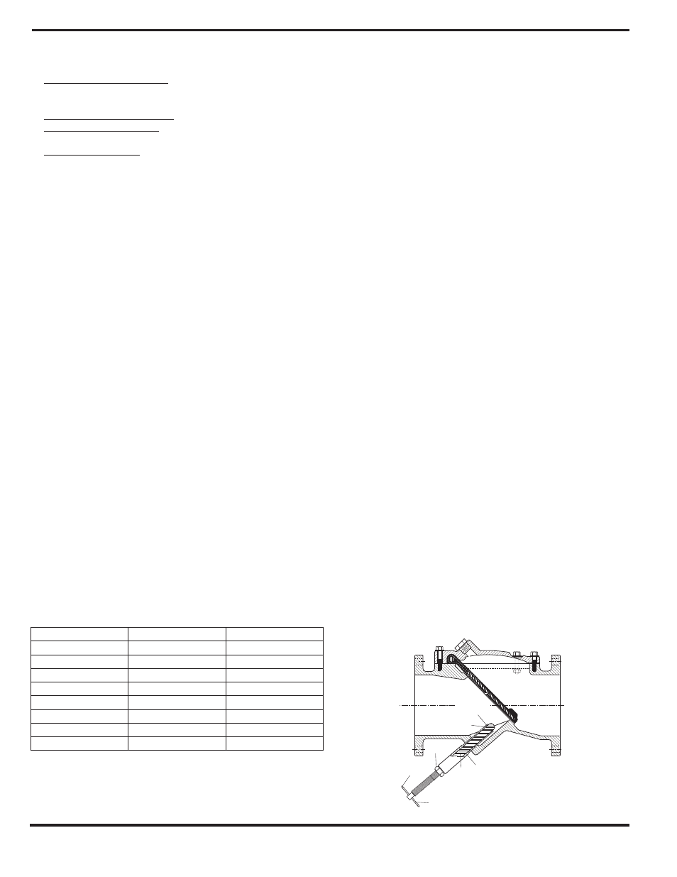
FIG. 3. BACKFLOW ACTUATOR ASSEMBLY
CLA-VAL
Copyright Cla-Val 2011 Printed in USA Specifications subject to change without notice.
P.O. Box 1325
• Newport Beach, CA 92659-0325 • Phone: 949-722-4800 • Fax: 949-548-5441 • E-mail: [email protected] • Website cla-val.com
©
N-584 Flex Check Valve
Valve Size (inches)
Cover Bolt Size
Torque (ft-lbs.)
2 - 2.5
1/2
75
3"
7/16
50
4
1/2
75
6
7/16
50
8
9/16
100
10
3/8
200
12 - 20
7/8
250
24
1
300
Cap
(Vinyl)
Bushing
(Brass)
Rod Wiper*
(Molythane)
O-Ring*
(Buna-n®)
Handle
(Stainless Steel)
Rod
(Stainless Steel)
Jam Nut
(Brass)