Cla-val, Dimensions – Cla-Val 60-73/660-73 Technical Manual User Manual
Page 12
Cla-Val Control Valves operate with maximum efficiency when mounted in horizontal piping with the main valve cover UP, however, other
positions are acceptable. Due to component size and weight of 8 inch and larger valves, installation with cover UP is advisable. We recommend
isolation valves be installed on inlet and outlet for maintenance. Adequate space above and around the valve for service personnel should be
considered essential. A regular maintenance program should be established based on the specific application data. However, we recommend a
thorough inspection be done at least once a year. Consult factory for specific recommendations.
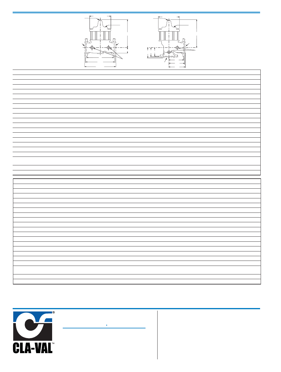
B (DIAMETER)
H
INLET
OUTLET
J
C
E
G
A
AA
AAA
OUTLET
INLET
B (DIAMETER)
C
G
H
J
D
DD
DDD
FFF
FF
F
Model 100-30
Dimensions
100-30 (Globe)
100-30 (Angle)
PO Box 1325 Newport Beach CA 92659-0325
Phone: 949-722-4800
Fax: 949-548-5441
CLA-VAL
CLA-VAL CANADA
CLA-VAL EUROPE
4687 Christie Drive
Beamsville, Ontario
Canada L0R 1B4
Phone: 905-563-4963
Fax: 905-563-4040
Chemin dés Mesanges 1
CH-1032 Romanel/
Lausanne, Switzerland
Phone: 41-21-643-15-55
Fax: 41-21-643-15-50
©
COPYRIGHT CLA-VAL 2009 Printed in USA
Specifications subject to change without notice.
www.cla-val.com
E-100-30 (R-11/09)
Represented By:
Valve Size
(Inches)
2
1
⁄
2
3
4
6
8
A Threaded
11.00
12.50
—
—
—
AA 150 ANSI
11.00
12.00
15.00
20.00
25.38
AAA 300 ANSI
11.62
13.25
15.62
21.00
26.38
B Dia.
8.00
9.12
11.50
15.75
20.00
C Max.
10.31
11.19
14.25
18.44
21.81
D Threaded
5.50
6.25
—
—
—
DD 150 ANSI
5.50
6.00
7.50
10.00
12.69
DDD 300 ANSI
5.81
6.63
7.81
10.50
13.19
E
1.69
2.06
3.19
4.31
5.31
F 150 ANSI
3.50
3.75
4.50
5.50
6.75
FF 300 ANSI
3.75
4.13
5.00
6.25
7.50
G Threaded
4.00
4.50
—
—
—
GG 150 ANSI
4.00
4.00
5.00
6.00
8.00
GGG 300 ANSI
4.31
4.38
5.31
6.50
8.50
H NPT Body Tapping
1
⁄
2
1
⁄
2
3
⁄
4
3
⁄
4
1
J NPT Cover Center Plug
1
⁄
2
1
⁄
2
3
⁄
4
3
⁄
4
1
K NPT Cover Tapping
1
⁄
2
1
⁄
2
3
⁄
4
3
⁄
4
1
Valve Stem Internal
Thread UNF
10-32
1
⁄
4
-28
1
⁄
4
-28
3
⁄
8
-24
3
⁄
8
-24
Stem Travel
0.7
0.8
1.1
1.7
2.3
Approx. Ship Wt. Lbs.
65
95
190
320
650
Valve Size
(mm)
65
80
100
150
200
A Threaded
279
318
—
—
—
AA 150 ANSI
279
305
381
508
645
AAA 300 ANSI
295
337
397
533
670
B Dia.
203
232
292
400
508
C Max.
262
284
362
468
554
D Threaded
140
159
—
—
—
DD 150 ANSI
140
152
191
254
322
DDD 300 ANSI
148
168
198
267
335
E
43
52
81
109
135
F 150 ANSI
89
95
114
140
171
FF 300 ANSI
95
105
127
159
191
G Threaded
102
114
—
—
—
GG 150 ANSI
102
102
127
152
203
GGG 300 ANSI
110
111
135
165
216
H NPT Body Tapping
1
⁄
2
1
⁄
2
3
⁄
4
3
⁄
4
1
J NPT Cover Center Plug
1
⁄
2
1
⁄
2
3
⁄
4
3
⁄
4
1
K NPT Cover Tapping
1
⁄
2
1
⁄
2
3
⁄
4
3
⁄
4
1
Valve Stem Internal
Thread UNF
10-32
1
⁄
4
-28
1
⁄
4
-28
3
⁄
8
-24
3
⁄
8
-24
Stem Travel
18
20
28
43
58
Approx. Ship Wt. Kgs.
30
43
86
145
295