X47a, Ejector, Model installation / operation / maintenance – Cla-Val 90-48/690-48 Technical Manual User Manual
Page 19
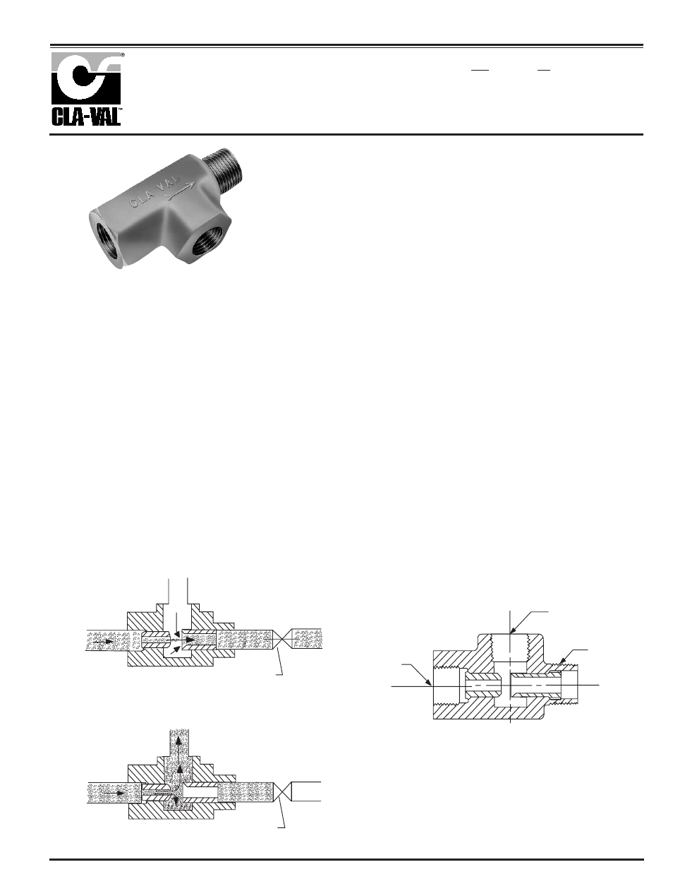
3/8 NPT
SUCTION PORT "B"
3/8 NPT
DISCHARGE
PORT "C"
3/8 NPT
PRESSURE
PORT "A"
PORT "C"
PILOT CONTROL
PILOT CONTROL CLOSED
PORT "B"
PORT "A"
PILOT CONTROL
PILOT CONTROL OPEN
PORT "A"
PORT "B"
PORT "C"
NOTE: OBTAIN AS COMPLETE ASSEMBLY ONLY. SPECIFY
NUMBER STAMPED ON SIDE OF EJECTOR WHEN RE-ORDERING.
DESCRIPTION
The Cla-Val Model X47A Ejector is a compact, precision fitting, incor-
porating a primary and a secondary jet, designed to create a low-pres-
sure area at the suction port.
DISASSEMBLY
Do not attempt to remove primary or secondary jets from X47A
Ejector housing.
CLEANING
After inspection, cleaning of the X47A can begin. Water service
usually will produce mineral or lime deposits on metal parts in con-
tact with water. These deposits can be cleaned by dipping the X47A
in a 5-percent muriatic acid solution just long enough for deposits to
dissolve. This will remove most of the common types of deposits
Caution: use extreme care when handling acid. If the deposit is
not removed by acid, then a fine grit (400) or dry sandpaper can be
used with water. Rinse parts in water before handling. An appro-
priate solvent can clean parts used in fueling service. Dry with com-
pressed air or a clean, lint-free cloth. Protect from damage and dust
until reassembled.
REPLACEMENT
If there is any sign of damage, or if there is the slightest doubt that
the X47A Ejector may not afford completely satisfactory operation,
replace it. Use Inspection steps as a guide. Neither the primary jet,
secondary jet, or bare housing is furnished as a replacement part.
Replace X47A Ejector as a complete unit.
OPERATION
The X47A Ejector is designed for use in a pilot control system on a Cla-
Val Main Valve. Pressure is applied to the inlet port (A). As the fluid
passes through the center portion of the X47A Ejector, the high veloc-
ity entrains particles of fluid from suction port (B), which results in a
reduced pressure at this port.
In actual operation, the pressure port (A) is connected to the upstream
side of the Main Valve; the discharge port (C) is connected to the Pilot
Control; and the suction port (B) is connected to the cover chamber of
the Main Valve.
Fluid line pressure enters at the inlet port (A). When the Pilot Control
is closed, no flow occurs through the X47A Ejector, and full line pres-
sure is directed into the Main Valve cover chamber, closing the Main
Valve tight. As the Pilot Control opens, and flow through the X47A
Ejector begins, pressure at the suction port (B) decreases until the
Main Valve is permitted to open. Further changes in the flow rate
resulting from opening and closing of the Pilot Control produce corre-
sponding changes in the flow through the Main Valve.
Ejector
X47A
INSPECTION
Inspect port threads for damage or evidence of cross-threading.
Check primary and secondary jets for clogging or embedded for-
eign particles. Check for breaks, cracks, fatigue, and other signs
of damage.
MODEL
INSTALLATION / OPERATION / MAINTENANCE