Cla-val, Hytrol main valve, X140-1 security cap option – Cla-Val 93-01/693-01 Quick Manual User Manual
Page 2
CLA-VAL
Copyright Cla-Val 2008 Printed in USA Specifications subject to change without notice.
P.O. Box 1325
• Newport Beach, CA 92659-0325 • Phone: 949-722-4800 • Fax: 949-548-5441 • E-mail: [email protected] • Website cla-val.com
©
N-93-01/693-01 (R-9/08)
H
3
5
2
D1
Y
B
S
C
4
B
A
1
D2
B
D3
INLET
OUTLET
SOLENOID DRAIN
TO ATMOSPHERE
CS3
3
1
2
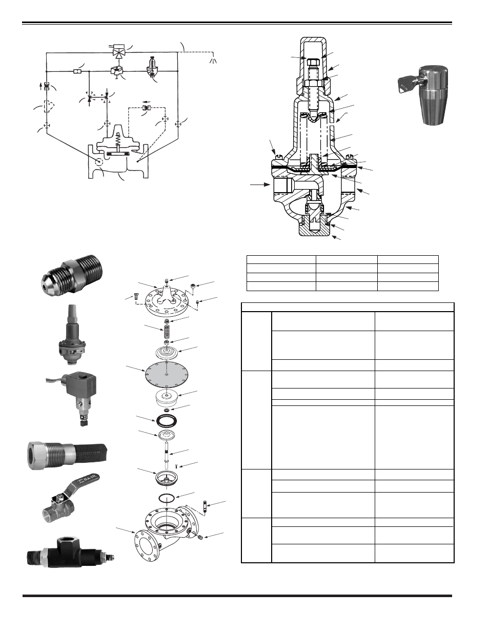
BASIC COMPONENTS
1 100-01 Hytrol (Main Valve)
100-20 600 Series Hytrol (Main Valve)
2 X58C Restriction Tube Fitting
3 CRD Pressure Reducing Control
4 100-01 Hytrol - Rev. Flow
5 CS3 Solenoid Control
OPTIONAL FEATURES
A X46A Flow Clean Strainer
B CK2 (Isolation Valves)
C CV Flow Control - Closing
D Check Valves with Isolation Valve
H Solenoid Drain to Atmosphere
S Opening Speed Control
Y X43 “Y” Strainer
For a more detailed IOM Manual go to www.cla-val.com or contact a Cla-Val Regional Sales Office.
CRD
93-01/693-01 SCHEMATIC
COVER
PIPE PLUG
COVER BEARING
SPRING
STEM NUT
DIAPHRAGM WASHER
DISC RETAINER
BODY
*
SPACER WASHERS
DISC GUIDE
SEAT
PIPE PLUG
STEM
SEAT O-RING
STUD
8" and Larger
*
DIAPHRAGM
*
DISC
*
Repair Parts
Seat Screw
8" and Larger
(Globe
or
Angle)
PIPE PLUG
HEX NUT
8" and Larger
Cover Bolt
6" and Smaller
CRD
X58C
CS3
X46A
CK2
CV
HYTROL MAIN VALVE
inlet
Cover vent
(3/8" NPT)
Cap
Adjusting Screw
Jam Nut
Cover
Spring
Hex Nut
Belleville Washer
Diaphragm Washer
Diaphragm*
Yoke
Body and Seat Assy
Disc Retainer Assy
Gasket*
Plug, Body
*Machine Screw
(Fil.Hd) 8 Req'd
Spring Guide
Pressure Setting
Adjusting Screw
(Turn Clockwise to
Increase Setting)
2.
3.
1.
3.
5.
A.
B.
C.
SYMPTOM
PROBABLE CAUSE
REMEDY
Main Valve
Fails to
Open
Main Valve
Fails to
Close
Fails to
Regulate
Solenoid
Valve
will not
Operate
No pressure at valve inlet
Main valve diaphragm assembly inoperative
Pressure Reducing Control (CRD) not opening:
1. No spring compression
2. Damaged spring
3. Spring guide not in place
4. Yoke dragging on inlet nozzle
Flow Control (CV) disc inoperative,
corrosion or excessive scale buildup on stem
Foreign matter between disc and seat or worn
disc. Scale on stem
Diaphragm damaged
X46 Flow Clean Strainer plugged, or
X43 “Y” Strainer plugged
CK2 (isolation valves) closed
Pressure Reducing Control (CRD)
remains open:
1. High spring compression
2. Damaged spring
3. Spring guide not in place
4. Yoke dragging on inlet nozzle
5. Diaphragm damaged or loose diaphragm
nut. Leakage from vent hole in cover
6. Worn or damaged disc retainer assembly
Air in main valve cover and/or tubing
Pressure Reducing Control (CRD)
yoke dragging on inlet nozzle
Pressure Reducing Control (CRD) spring
not in correct range to control
Solenoid voltage
Burned out solenoid coil
Check inlet pressure Disassemble,
clean and polish stem, disc guide,
replace defective parts
1. Tighten adjusting screw
2. Disassemble and replace
3. Assemble properly
4. Assemble properly
Disassemble, clean and polish stem,
Replace worn parts
Disassemble main valve
remove foreign matter, clean or
replace damaged parts
Remove and clean or replace
units
Open isolation valves
1. Back off adjusting screw
2. Disassemble and remove
obstruction
3. Disassemble and replace
4. Assemble properly
5. Disassemble, replace diaphragm
and/or tighten nut
6. Remove and replace
Loosen top cover plug and/or
tubing fining and bleed air
Assemble properly
Check outlet pressure require-
ments and compare existing spring
with chart
Check voltage across coil leads
must be minimum of 85% of
nameplate rating
Check for open circuit coil
Replace coil
SOLENOID SYMPTOMS
CRD adjust range (psi)
Spring Color
psi change per turn*
2 - 30
Stainless Steel
3
15 - 75
Red
9
30 - 300
* approximate. Use gauge at valve outlet to set
Green
27
X140-1
Security Cap
Option