Installation, Instalación – Infinity Drain TDB Series Installation Instructions User Manual
Page 3
3
Installation
1. Set bonded flange into a wet pre laid bed of
mortar and allow bonded flange drain body (C)
to recess into subfloor. Connect the drain body
(C) to existing waste line using PVC cement or
ABS pipe cement. If no access to drain pipe is
available from below, prep outlet of the bonded
flange (C) with PVC or ABS primer and cement
and push fit into existing waste line as you
set the bonded flange into the mortar. Ensure
that drain assembly (C) is
level. Remove top
threaded ring (C1) from drain body (C2).
Instalación
1. Coloque bonded flange en el húmedo
pre-establecido de mortero y permita el
drenaje de bonded flange (C) que rebaje
en el subsuelo. Conecte el drenaje (C) a la
actual línea de desecho usando cemento de
PVC o cemento de tubería de ABS. Si no hay
acceso al tubo de desagüe de abajo, preparar
la salida del bonded flange en el mortero.
Asegure que la ensamble para desagüe (C)
este
nivelado. Elimine la parte superior del
anillo roscador (C1) del desagüe (C2).
Note: The outlet of the bonded flange
drain body (C2) can be made to be used
with a 2”, 3” OR 4” waste line by cutting
the outlet section down to the desired
section size.
Tenga en cuenta: La salida del bonded
flange desagüe (C2) se puede hacer
para ser utilizado con 2”, 3” U 4” línea de
desechos cortando la sección de salida al
tamaño de la sección deseada.
2.Install backer board, cement board, or
other desired backing material on to framed
walls as per local code.
3. Spread a mortar bed across the intended
shower area. Ensure the starting height of
the mortar bed at the drain is flush with the
flange of the drain body (C2) at the drain. Pitch
this mortar bed in four directions towards the
drain body (C2).
2. Instale los paneles, tablero de cemento,
u otro material de soporte deseada a los
marcos de paredes según las normas locales.
3. Propagación el mortero a través de la zona
de ducha prevista. Asegure que la altura
inicial del mortero en el drenaje este a ras con
el desagüe (C2). Inclina esta capa de mortero
en cuatro direcciones hacia el cuerpo de
desagüe (C2).
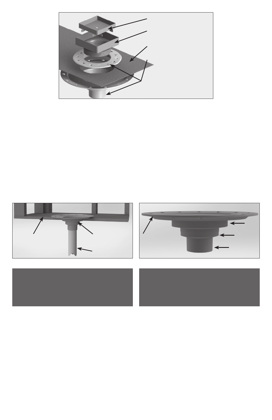
(A) Strainer
(B) Throat
Liquid/Fabric Waterproofing
(C) Bonded Flange Drain
Body BFA/BFP
(C1)
(C2)
(C2) Bonded Flange
Drain Body
Waste Line Pipe
Subfloor
Flange
4” Section
3” Section
2” Section