Installation and operation, Installation and operation, cont’d, Installation overview – Extron Electronics VSC 75 User Guide User Manual
Page 7: Mounting the vsc 75
VSC 75 Installation and Operation
VSC 75 Installation and Operation
Installation and Operation, cont’d
2-3
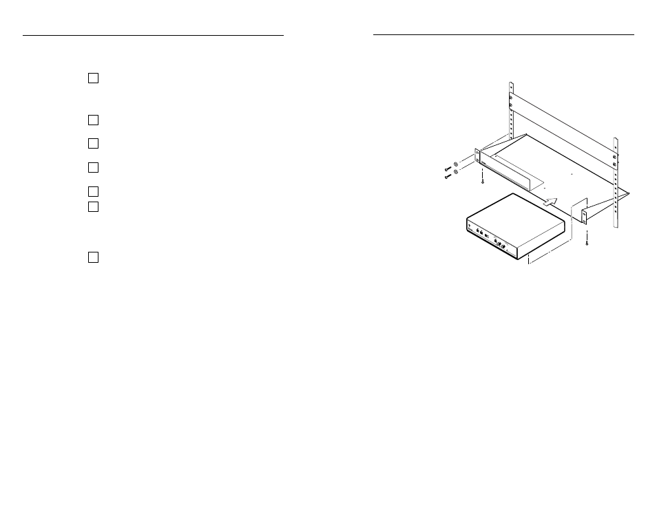
screws from the underside of the shelf, and securely
fasten them into diagonally-opposite corners as
shown in figure 2.
Figure 2 — Rack mounting
4
.
Attach the false front panel (provided with the rack
shelf) to the unoccupied side of the rack (as shown
above), or install a second half-rack-width device in
that side by repeating steps 1 – 3.
5
.
Attach the rack shelf to the rack using four 10-32 x ¾”
bolts (provided). Insert the bolts through #10 beveled
washers, then through the holes in the rack ears and
rack, as shown above.
Installation and Operation
Installation Overview
To install and set up the VSC 75, follow these basic steps:
1
Turn all of the equipment off. Make sure that the
source computer, the VSC 75, and the output devices
(projector, monitors) are turned off and disconnected
from the power source.
2
Mount the scan converter. See “Mounting the
VSC 75” on page 2-2.
3
Set the rear panel toggle and DIP switches. See “Rear
Panel Features” on page 2-6.
4
Attach the cables. See “Cabling” on page 2-7 and
“Rear Panel Features” on page 2-6.
5
Connect power cords and turn on all the equipment.
6
The image should now appear. If not, ensure that all
devices are plugged in and receiving power. Check
the cabling and rear panel switches, and make
adjustments as needed. Refer to “Troubleshooting”
on page 2-11 if needed.
7
Optimize the image for your display environment.
See “Optimizing the Image” on page 2-10.
Mounting the VSC 75
Select tabletop placement or rack mounting. Follow the
appropriate installation instructions on these two pages.
Tabletop/desktop placement
For tabletop or desktop placement only, install the self-
adhesive rubber feet/pads (provided) onto the four corners
of the bottom of the enclosure.
Rack mounting
1
.
If feet were installed on the bottom of the VSC 75,
remove them.
2
.
Place the VSC 75 on one half of the 1U (one unit high,
one unit wide) rack shelf (part #60-190-01). Align the
front of the VSC 75 with the front of the shelf, and
align the threaded holes on the bottom of the VSC 75
with the holes in the rack shelf.
3
.
Attach the VSC 75 to the rack shelf with the two
provided 4-40 x 1/8” machine screws. Insert the
2-2
(2) 4-40 x 1/8" Screws
Use 2 mounting holes on
opposite corners
False front panel
uses 2 front holes
MIN/
MAX
FREEZE
SIZE
TEST
FLICKER
FIL
TER
I
II
VSC 75
SCAN CONVER
TER
CENTERING/PAN SIZE