Installation and operation, cont’d, Mac-hv/vga cable connector pin assignments, Pc computer mac computer – Extron Electronics VSC 75 User Guide User Manual
Page 10: Vsc 75 installation and operation, Figure 6 — a typical vsc 75 system application, Figure 5 — mac-vga cable local monitor connections
VSC 75 Installation and Operation
VSC 75 Installation and Operation
Installation and Operation, cont’d
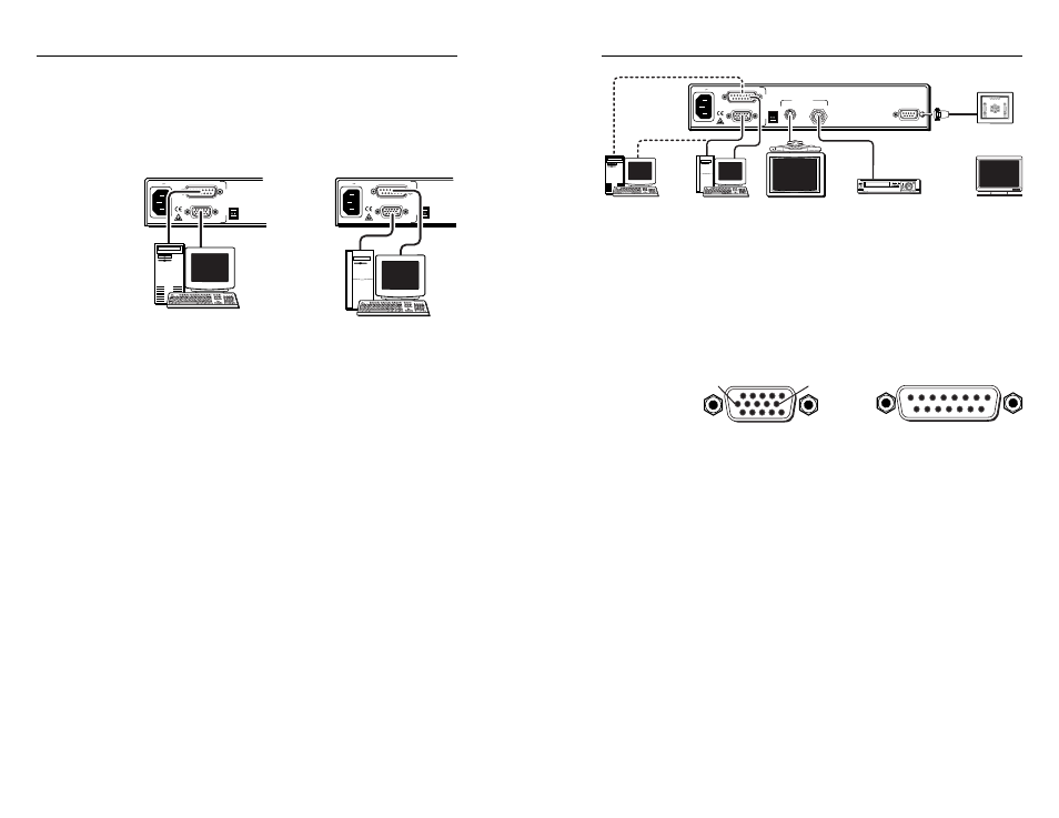
Figure 6 — A typical VSC 75 system
application
Mac-HV/VGA cable connector pin assignments
The illustration below shows the pin locations on the 15-pin
connectors at opposite ends of the Mac-HV/VGA cable that
is used for connecting the computer to the VSC 75.
Figure 7 — VGA (15-pin HD) and Mac (15-pin D)
connector pin locations
The table on the next page lists signals and their pin
assignments for both the VGA (15-pin HD) and
Mac (15-pin D) connectors of this cable.
2-9
D15 Pin Locations
Male
1
8
9
15
HD15 Pin Locations
Male
1
5
11
15
10
6
2-8
the other (15-pin D) end into the computer’s
video output connector.
•
If the source computer is a VGA-type PC, plug
the Mac (15-pin D) end into the VSC 75, and plug
the other (15-pin HD) end into the computer’s
video output connector.
Figure 5 — Mac-VGA cable local monitor
connections
If a local monitor will not be used, set the 75 Ohm DIP
switch to On (75 ohms), or install a termination
adapter on the unused local monitor connector.
3
.
Set the PAL Out (NTSC/PAL output) DIP switch. Use
“Rear Panel Features” on page 2-6 as a guide.
4
.
Connect the composite video display or recording
device to the composite video output BNC connector.
5
.
Connect a cable from the input of the second video
display/recording device (projector, monitor, VCR) to
the S-video output 4-pin mini-DIN connector.
6
.
If RS-232 control will be used, connect the RS-232
remote controller or computer to the RS-232 connector.
7
.
Connect power cords and turn on all the equipment.
The system is now ready for operation.
Figure 6 shows typical system installation and cable
connections.
50/60 Hz
100-240 V 0.3A
P
AL OUT
75 OHM
MAC
VGA
I
N
P
U
T
S
50/60 Hz
100-240 V 0.3A
P
AL OUT
75 OHM
MAC
VGA
I
N
P
U
T
S
PC Computer
Mac Computer
50/60 Hz
100-240 V 0.3A
S-VIDEO
RS-232
P
AL OUT
75 OHM
VIDEO
MAC
VGA
I
N
P
U
T
S
OUTPUTS
RS-232 Control
PC Computer
Mac Computer
or
or
Videoconference
System (S-video)
Monitor
VCR
(Composite Video)
VSC 75 Rear Panel