Installation and operation, cont’d, Rear panel features, Caution – Extron Electronics SW2 VGA DA2 AF R User Guide Rev. A User Manual
Page 9
SW2 VGA DA2 AF R • Installation and Operation
SW2 VGA DA2 AF R • Installation and Operation
Installation and Operation, cont’d
2-9
8
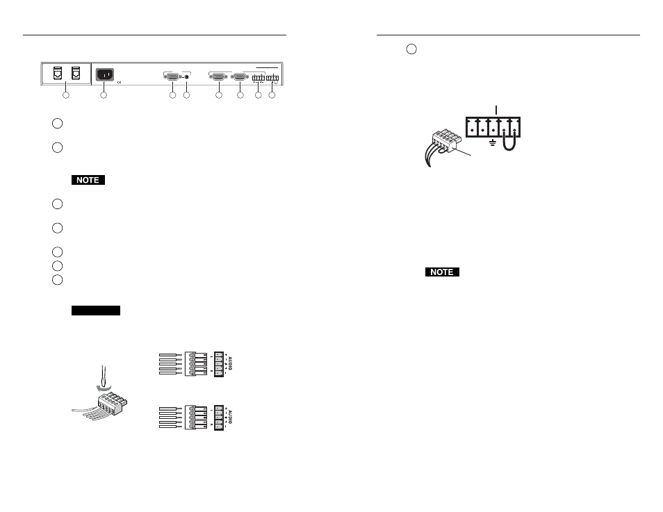
Autoswitching/Contact closure connector
— Connect a contact
closure control device to the left three pins of this 3.5 mm,
5-pole captive screw connector.
• Pin 1 selects input 1 when connected to ground (pin 3).
• Pin 2 selects input 2 when connected to ground (pin 3).
• Pin 3 connects to the ground wire.
Contact Closure Control
Jumper pins 4 & 5 for
autoswitching.
1 2
CONTACT AUTO-SW
• Pins 4 and 5 if jumpered/shorted together will turn the auto-
switching mode
on. When the auto-switching mode is on,
the switcher automatically switches to the input that has an
active sync signal.
If both inputs have an active sync signal present, the
highest input, input 2, will be used, and the input 2
indicator LED will light. If no active sync signal is present,
neither input indicator LED will light.
Auto-switching overrides manual input selection. If
auto-switching is on, contact closure and front panel
input selection will be disabled.
• If pins 4 and 5 are not connected, manual switching is
enabled. Selections can be made via the front panel
selection switches and the contact closure device.
If no active sync signal is present, the input 2 indicator LED
will still light.
2-8
Rear Panel Features
100-240V 5.5A MAX.
50/60 Hz
INPUT
1
1 2
OUTPUTS
A (LOCAL MONITOR)
B
SW2 VGA DA2 AF R
CONTACT AUTO-SW
1
2
3
4
5
6
7
8
1
Cable access opening
— Cables attached to the A/V pass-
through architectural adapter plates exit the enclosure here.
2
AC power input connector
— Connect a standard IEC AC
power cord here for power input (100 VAC to 120 VAC,
50/60 Hz).
This unit can operate at 100 to 240 VAC, 50/60 Hz with
the proper power cords.
3
Input 1 video
— 15-pin HD female VGA connector (Input 2
video is located on the front panel.)
4
Input 1 audio
— 3.5 mm female audio jack (Input 2 audio is
located on the front panel.)
5
Output A (Local Monitor)
— 15-pin HD female VGA connector
6
Output B
— 15-pin HD female VGA connector
7
Stereo audio output connector
— Balanced or unbalanced audio
can be output via this 3.5 mm, 5-pole captive screw connector.
The audio output cable should be wired as shown below.
CAUTION
Connect the sleeve to ground (GND). Connecting
the sleeve to a negative (-) terminal will damage the
audio output circuits.
Unbalanced Output
Tip
See Caution
Sleeve (s)
Tip
See Warning
Balanced Output
Tip
Ring
Sleeve (s)
Tip
Ring
Wiring the audio output connector