Extron Electronics SW2 VGA DA2 AF R User Guide Rev. A User Manual
Page 10
SW2 VGA DA2 AF R • Installation and Operation
SW2 VGA DA2 AF R • Installation and Operation
Installation and Operation, cont’d
2-11
10
0-2
40
5
0/6
0 H
z 0
.5A
IN
PU
T
2
1
2
A
S
AS
/R
EM
OT
E
OU
TP
UT
S
B
Rear
Power
Network
Connection
LCD Projector
Laptop or VGA Computer
Monitor
Stereo Audio
UN
SWIT
CHED
10
0-2
40
0.
5A
M
AX
.
AU
TO
SW
ITC
H
AC
TIV
E
SW
2
VG
A
DA
2 A
F R
1
2
IN
PU
T
1
Extron
SW2 VGA DA2 AF R
Switcher
Front
AC
Power
LBC w/ Audio
Cable
Network
Connection
Laptop
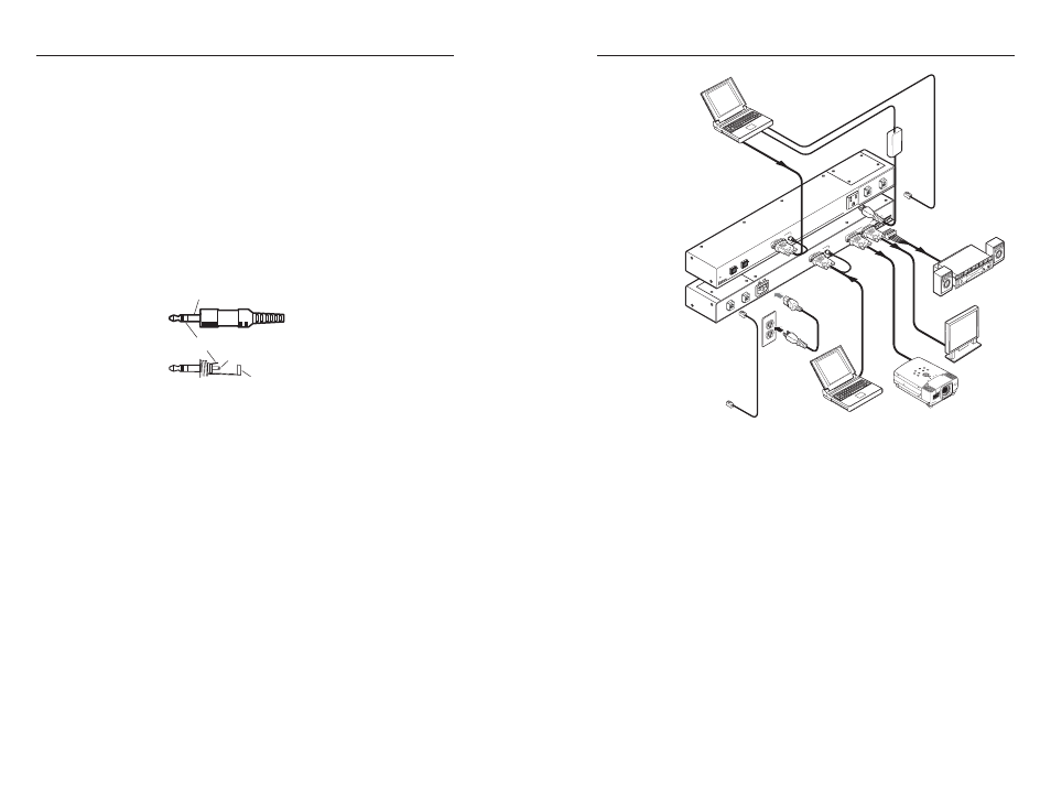
A typical SW2 VGA DA2 AF R installation
Operation
1.
Make sure that all the input and output devices and the
switcher are powered on.
2.
If the switcher is in manual switching mode, select an input
from the front panel buttons or by using the contact
closure controller.
3.
If the switcher is in auto-switching mode (rear panel
Contact/Auto-sw pins 4 and 5 are jumpered together), the
switcher will automatically select the highest numbered
input with an active sync signal.
4.
The image should now appear on screen, and sound from
the audio source should be audible.
2-10
Cabling
Attach cables to the switcher as detailed in the steps below. The
diagram in this section shows how the system looks when
cabling is finished.
1.
Attach the VGA/SVGA/XGA computers’ output cables to
the switcher via the 15-pin HD female input connectors. If
the computers will provide the audio input, VGA with
audio combination cables, such as the Extron VGA HRA
series (#26-490-01 to #26-490-04), can be used.
2.
Connect the cables from the stereo audio sources
(computers or other devices such as CD players or tape
decks) to the audio input jacks. The audio plug should be
wired as shown below.
Tip (L)
Sleeve (Gnd)
Tip (L)
Ring (R)
Sleeve (Gnd)
3.
Connect VGA cables from the switcher’s 15-pin HD female
output connectors to the display devices (projectors,
monitors).
4.
Connect the speakers’ or other audio output device’s cable
to the switcher’s audio output captive screw connector.
5.
Attach the contact closure device to the left three pins of
the 5-pole captive screw Contact/Auto-sw connector.
6.
Connect power cords and turn on the devices in the
following order: display and audio output devices
(projectors, monitors, speakers), contact closure controller,
SW2 VGA DA2 AF R switcher, and input devices
(computers, audio sources).