Application diagram, Step 4 — connect power, Grounding guidelines – Extron Electronics TP Series Transmitters Setup Guide User Manual
Page 2: Step 5 — set dip switches, Step 6 — adjust horizontal shift
68-546-01 Rev. B
02 13
Extron Headquarters
+1.800.633.9876 (Inside USA/Canada Only)
Extron USA - West
Extron USA - East
+1.714.491.1500 +1.919.850.1000
+1.714.491.1517 FAX
+1.919.850.1001 FAX
Extron Europe
+800.3987.6673
(Inside Europe Only)
+31.33.453.4040
+31.33.453.4050 FAX
Extron Asia
800.3987.6673
(Inside Asia Only)
+65.6383.4400
+65.6383.4664 FAX
Extron Japan
+81.3.3511.7655
+81.3.3511.7656 FAX
Extron China
+4000. 398766
(Inside China Only)
+86.21.3760.1568
+86.21.3760.1566 FAX
Extron Middle East
+971.4.299.1800
+971.4.299.1880 FAX
Extron Korea
+82.2.3444.1571
+82.2.3444.1575 FAX
Extron India
1800.3070.3777
(Inside India Only)
+91.80.3055.3777
+91.80.3055.3737 FAX
© 2013 Extron Electronics All rights reserved.
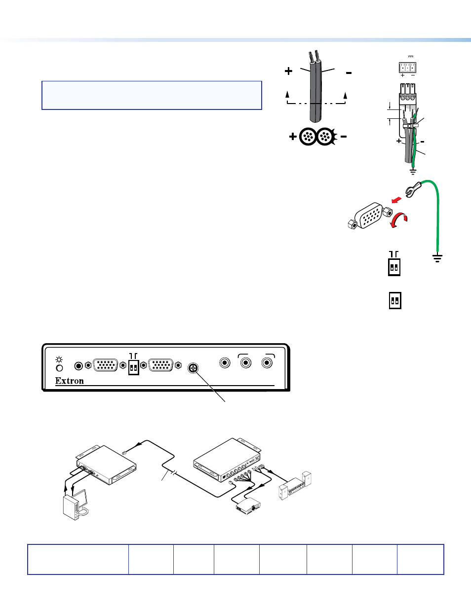
Step 4 — Connect Power
Plug the included external 15 VDC power supply into the 3-pole captive
screw connector. Wire the connector as shown at right.
NOTE:
The TP T 15HD A and TP T 15HD AV can be powered via
the attached receiver (except the TP R 15HD A) for cable runs of
300 feet (91.4 m) or less.
Grounding guidelines
Any Extron TP T series transmitter can be adversely affected by
electrostatic discharge (ESD) if it is not grounded correctly.
To prevent malfunctions or product damage, an experienced installer can
correctly ground an Extron TP T transmitter in either of two ways:
•
Ground the power input port — Insert one end of the grounding wire
to the negative or ground pin on the power input connector (see the image at top right). Tie the
other end of the wire to an earth ground.
•
Ground the chassis — Use a connector hex nut (see the image at right). Tie the other end of
the wire to an earth ground.
If you have any questions about how to ground a product in a specific application, contact an
Extron technical support specialist.
Step 5 — Set DIP Switches
•
ID Pin 4 and ID Pin 11 (front panel) — Set these switches to Off (down) if a local monitor is
connected, or to On (up) if not.
•
DDSP (back panel) — Set this switch to On (up), if needed, to enable Digital Display Sync Processing.
Set the switch to Off (down) for displays that cannot handle processed sync.
Step 6 — Adjust Horizontal Shift
While viewing the display, use a small screwdriver to turn the H-Shift (TP T 15HD A) or PC H-Shift (TP T 15HD AV) potentiometer
on the front panel to adjust the side-to-side image placement.
PC
H-SHIFT
TP T 15HD AV
AUDIO
VIDEO
L
R
AUDIO
BUFFERED
COMPUTER
INPUT
LOCAL MONITOR
ID PIN 4
ID PIN 11
Horizontal Shift Potentiometer
Application Diagram
TP T 15HD A
H-SHIFT
BUF
FER
ED
COMPUTER
INPUT
AUDIO
ID PIN 4
ID PIN 11
LOC
AL M
ONIT
OR
Extron
TP R BNC A
Twisted Pair Receiver
Extron
TP T 15HD A
Twisted Pair
Transmitter
RGB INPUT
RGB OUTPUT
R
G
B
H/H
V
V
A
AU
DIO
L
R
B
SO
G C SYNC
PO
WE
R
15V .5A DC
L
R
Computer
Extron
Enhanced
Skew-Free™ A/V
UTP Cable
Audio
Sound System
LCD Projector
Power Supply
Output Cord
SECTION A–A
Ridges
Smooth
A
A
POWER
12V
xA MAX
Rear
Panel
Tie
Wrap
Ridges
Earth
Ground
3/16"
(5 mm)
Max.
ID PIN 4
ID PIN 11
DDSP
SP
ARE