Extron Electronics TP Series Transmitters Setup Guide User Manual
Tp transmitters • setup guide, Pre-installation — jumper settings, Installation
TP Transmitters • Setup Guide
This guide provides quick start instructions for an experienced installer to set up and operate the TP Transmitter Series products.
Pre-installation — Jumper Settings
The TP T 15HD A and TP T 15HD AV are factory configured to transmit RGB video. You can reconfigure them
to transmit component, S-video, or composite video by using a jumper to connect pins 1 and 2 at locations
J1 and J2 on the main circuit board (see the illustration at right).
NOTE:
If using the TP T 15HD AV with a TPX 88X transmitter or with an older, unmodified receiver,
see “Audio Jumpers” in the TP T Series Transmitters User’s Manual for information on audio jumper
placement for compatibility.
CAUTIONS:
•
Always disconnect power to the unit before opening the enclosure.
•
Wear a wrist grounding strap when handling the circuit board.
Installation
Step 1 — Mount the Unit
Turn off or disconnect power to all equipment, and mount the transmitter as desired.
Step 2 — Connect Inputs
Attach input cables to the audio and video connectors as applicable for your TP T model.
•
Composite video — Connect a composite video source device to the Video RCA jack
(TP T 15HD AV) or the G pin of the Computer Input 15-pin HD connector (TP T 15HD A).
•
S-video — Connect an S-video source device to pins R (chroma) and G (luma) of the
Computer Input 15-pin HD connector.
•
Component video — Connect a source device to pins R (R-Y), G (Y), and B (B-Y) of the
Computer Input HD connector.
•
RGBHV computer video — Connect an RGB source device to the female Computer Input HD connector.
•
RGBS computer video — Connect an RGB source device to the female Computer Input HD connector.
•
Audio input — Connect PC audio to the 3.5 mm TRS stereo jack.
•
Audio input L and R pair — Connect left and right stereo audio to the RCA connector pair (TP T 15HD AV only).
NOTE:
Input only analog line level audio signals on these connectors.
Step 3 — Connect Outputs
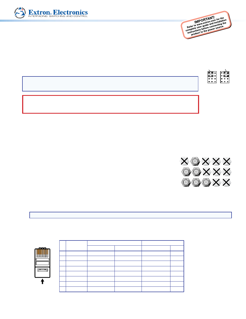
•
Connect the RJ-45 cable from a TP receiver to an RJ-45 port on the TP transmitter. Terminate the cable ends according to
the TIA/EIA T 568A wiring standard (see the table below).
Pin Wire Color
RGB Video and Audio
AV Video and Audio
Signal
Level
Signal
Level
1
White-green
Red/V. sync+
±0.35 V
Video+
+0.35 V
2
Green
Red/V. sync–
±0.35 V
Video–
–0.35 V
3
White-orange Audio and power +15 V ±0.5 V
+15 V
4
Blue
Green+
+0.35 V
Reserved
None
5
White-blue
Green–
–0.35 V
Reserved
None
6
Orange
Audio and power
Audio+* & power+
Audio–* & power–
±0.5 V
0 V
7
White-brown
Blue/H. sync+
±0.35 V
Reserved
None
8
Brown
*Audio can be connected to wire pair 7 and 8 with a jumper.
Blue/H. sync–
±0.35 V
Reserved
None
12345678
RJ-45 Connector
Insert Twisted
Pair Wires
Pins:
•
If desired, connect a local monitor video cable to the Buffered Local Monitor port.
Component,
S-video,
Composite
1
1
1
1
1
1
RGB
TP T 15HD A
TP T 15HD AV
R
G
B
H/HV
V
R
G
B
H/HV
V
R
G
B
H/HV
V