Installation and operation, cont’d, Setting internal jumpers – Extron Electronics RGB 158xi VGA User Guide User Manual
Page 10
RGB 138
xi, RGB 158xi Installation and Operation
RGB 138
xi, RGB 158xi Installation and Operation
Installation and Operation, cont’d
6
Stereo audio output connector
— This 3.5 mm,
5-conductor captive screw connector is used for
audio output. See “Cabling” in this chapter for a
wiring guide.
Setting Internal Jumpers
The jumpers inside the interface(s) are set at the factory to meet
the requirements of most systems. However, you can change
a jumper setting to meet the needs of a particular system.
Changes to internal jumper settings must be
performed by authorized service personnel only.
The user-configurable, internal jumpers control the
following functions:
• horizontal and vertical sync polarity, and
• vertical sync pulse width.
Follow these steps to change the jumper settings. The
RGB 138
xi is shown for illustration, but the steps apply to
both models.
1. Remove power from the interface (if it is connected) by
disconnecting the AC power cord from the unit.
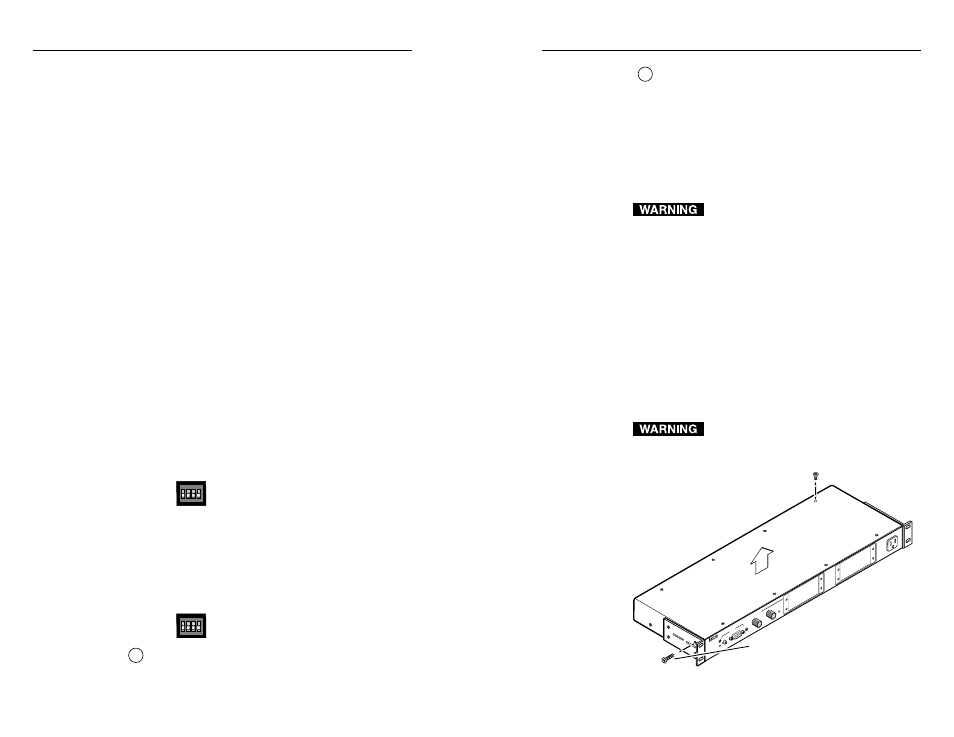
2. Open the cover of the interface (the top half of the
enclosure), as shown below. Remove the screws
from the enclosure, and lift the cover straight up.
Do not touch any switches or electronic
components inside the interface. Doing so
could damage the interface.
RGB 138
xi
RGB 138 xi
INP
UT
S
AU
DIO
AN
AL
OG
UNSWITCHED
600 W
ATTS
MAX.
MIN
/MA
X
MB
C
PO
WE
R
UN
IVE
RS
AL
IN
TE
RF
AC
E
W
/AD
SP
Remove #8 Screws
(4 Places) Each Side
and Bracket, if Present
Remove (12)
Screws
Lift Cover
Straight Up
Opening the interface cover
2-9
properly. Flagging or bending at the top of the
video image is a sign that the serration pulses
should be removed.
ON — When this switch is set to On, serration
pulses will be output in the vertical sync
interval.
OFF — When this switch is set to Off, serration
pulses will not be output.
4 — 75 Ohm (video input termination) —
RGB 138
xi only — Video termination is
accomplished in a number of ways when using a
universal interface like the RGB 138
xi:
1. Setting the 75 ohm termination switch on the
interface when using an MBC cable without a
local monitor attached,
2. Using a laptop breakout cable (LBC)
connected to a laptop or desktop computer
with no local monitor,
3. Connecting a local monitor to the breakout
from an MBC cable,
4. Using a termination adapter with an MBC
cable and no local monitor attached, or
5. Using an MBC buffer cable.
The input to the interface is high impedance, and
for the video signal to be at a proper level (not
blooming) 75 ohm termination is needed for the
computer signal. The switch provides a method
of termination to prevent blooming
when a monitor breakout cable is used
but no local monitor or termination
adapter is connected.
ON — The RGB 138
xi provides 75 ohm video
input termination.
OFF — The RGB 138
xi provides Hi Z (high
impedance) video input termination.
4 — SPARE — RGB 158
xi only
This DIP switch does not have a
function in the RGB 158
xi.
5
BNC output connectors
— These BNC female
connectors are for red, green, and blue video output,
and horizontal, vertical and composite sync output.
SOG
DDSP
SERR
75 Ohm
SOG
DDSP
SERR
SPARE
2-8