Step 4 — final installation – Extron Electronics PCM 340 User Manual
Page 3
3
f.
Install appropriate anchors or lag eye bolts for the structural
ceiling into each drilled hole.
g.
Loop the safety cable through the center anchor or lag eye bolt,
attach it to the plate center holes (figure 6) and secure it with the
cable clamps.
h.
Cut appropriate lengths of the supplied tie wire.
Loop the wire through the anchors or lag eye bolts and the
turnbuckles, then twist the wire around itself at least five times.
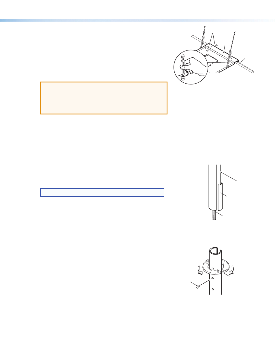
i.
Tighten the turnbuckles by hand (see figure 6), and level the plate
so that it just rests on the grid.
ATTENTION:
Potential Damage to Property.
• The four hanging wires should be taut, taking
the full weight of the completed installation.
• Overtightening the turnbuckles could cause
the T-bar assembly to be lifted, making the
suspended ceiling bowed and unsafe.
j.
Tighten the four T-frame securing screws on the PCM.
k.
Push the slotted pipe up through the hole into the adapter plate
and tighten the location and set screws to secure the pipe in place.
Step 4 — Final Installation.
a.
Install the projector assembly and lock it into place.
b.
Tuck the signal cables into the slotted pipe and firmly snap
the trim piece into place (see figure 7).
NOTE:
The trim piece can be cut to the desired length.
c.
Open the escutcheon ring and, with the tabs uppermost,fit the ring
around the slotted pipe (see figure 8), then close it. Slide the ring
up until it is snug against the ceiling tile.
d.
Insert the hole plugs into the remaining open holes in the visible
part of the pipe.
e.
Complete any further device installation according to the relevant
device manual.
PCM
T-frame
Adjust the turnbuckles to take
up any slack in the hanging wire.
Secure PCM to frame
(from either side)
Slotted
Projector Pipe
Snap-in
Trim Piece
Device Cables
Escutcheon
Ring
Hole Plug
Figure 6.
Adjust Turnbuckles.
Figure 7.
Snap in Trim Piece.
Figure 8.
Fit Ring and Hole Plugs.