Front panel configuration port, Installation, cont’d, Figure 2-8 — front panel configuration port – Extron Electronics CrossPoint 300 Series User Manual
Page 22
Installation, cont’d
CrossPoint 300 Matrix Switchers • Installation
2-8
Front Panel Configuration Port
ENTER
PRESET
VIEW
ESC
RGBHV
AUDIO
CONTROL
IO
WIDEBAND MATRIX SWITCHER with ADSP™
CROSSPOINT 300 SERIES
CONFIG
9
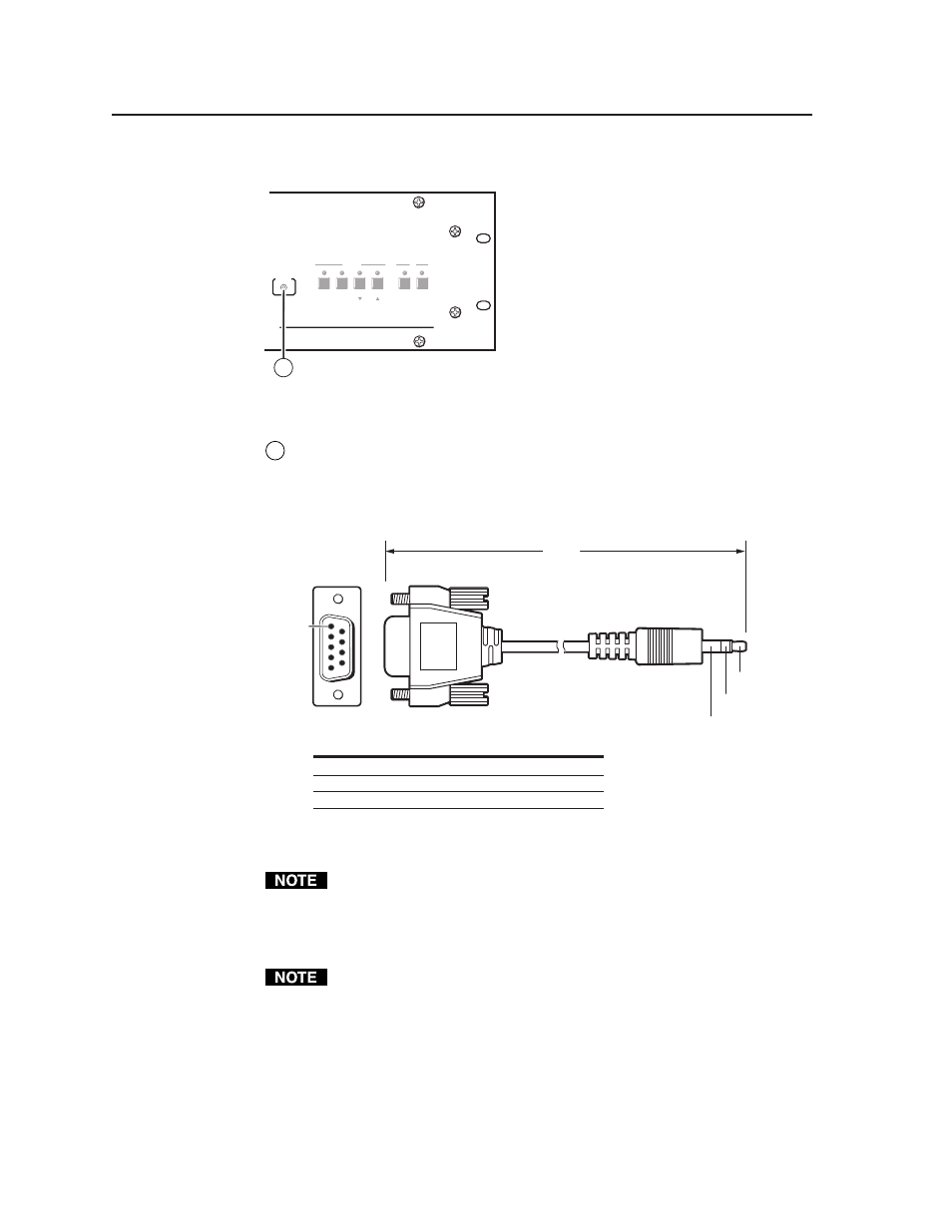
Figure 2-8 — Front panel configuration port
9
Configuration port
— This 2.5 mm mini stereo jack serves the same serial
communications function as the rear panel Remote port, but it is easier to
access than the rear port after the matrix switcher has been installed and
cabled. The optional 9-pin D to 2.5 mm mini jack TRS RS-232 cable,
part #70-335-01 (figure 2-9), can be used for this connection.
6 feet
(1.8 m)
Part #70-335-01
5
1
9
6
Sleeve (Gnd)
Ring
Tip
9-pin D
Connection
TRS Plug
Pin 2
Computer's RX line
Tip
Pin
3
Computer's
TX
line
Ring
Pin 5
Computer's signal ground
Sleeve
Figure 2-9 — Optional 9-pin TRS RS-232 cable
This port is independent of the rear panel Remote port and is not affected by
changes to the rear panel port’s protocol. This front panel port’s protocol can
be changed, under SIS command control only. See the Command/Response
table for IP SIS commands, in chapter 4, “Programmer’s Guide”, to configure
all ports under SIS control.
A front panel Configuration port connection and a rear panel Remote port
connection can both be active at the same time.