Making connections and rear panel settings, Making connections and rear panel settings -4, Installation, cont’d – Extron Electronics MAV Plus Series Setup Guide User Manual
Page 9
CrossPoint / MAV Matrix Switchers • Installation
Installation, cont’d
2-4
CrossPoint / MAV Matrix Switchers • Installation
2-5
Refer also to the CrossPoint 450 Plus / CrossPoint Ultra / MAV Plus User’s Manual at www.extron.com.
Refer also to the CrossPoint 450 Plus / CrossPoint Ultra / MAV Plus User’s Manual at www.extron.com.
Making connections and rear panel settings
C
Turn off power to the input and output devices, and
disconnect their power cords.
N
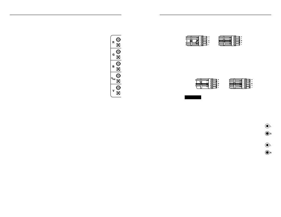
Video connectors are grouped by video plane.
Connect the input or output on each video plane
to the corresponding connector in the correct
group. Refer to the
CrossPoint 450 Plus /
CrossPoint Ultra / MAV Plus Switcher
Manual to connect the various video formats to
and from the various models if you are not sure.
a
Video inputs — Connect RGBHV, RGBS, RGsB,
RsGsBs, component/HDTV video, S-video, or
composite video sources, as appropriate to your
switcher model's video format and matrix size.
b
Video outputs — Connect RGBHV, RGBS, RGsB,
RsGsBs, component/HDTV video, S-video, or
composite video displays, as appropriate to your
switcher model's video format and matrix size.
c
Sync termination switches (CrossPoint switchers) —
Set the switches as necessary to condition non-TTL sync levels
greater than 5 Vp-p. Sync termination enables the sync to be
properly passed from input to selected output(s).
N
CrossPoint 450 Plus switchers have Sync termination
switches for inputs 1 through 8.
CrossPoint Ultra switchers have Sync termination
switches for inputs 1 through 4.
The matrix switchers have two sets of sync termination
switches; one for horizontal or combined sync and a second
set for vertical sync.
510 ohms —
The default position, suitable for most video.
75 ohms —
Typically required only for an input with non-TTL
sync (greater than 5 V p-p).
N
An input that produces an out of sync display, a display
that is rolling vertically and/or tearing horizontally, could
indicate a non-TTL sync input. If you are not sure, check
the specifications in the user’s manual for the input device.
1
2
1
2
1
2
1
2
1
2
d
Connections for balanced and unbalanced audio inputs (most
audio models) —
Connect balanced or unbalanced
stereo
audio inputs to these 5-pole captive screw connectors.
L
R
Unbalanced Input
Balanced Input
(high impedance)
(high impedance)
Ring
Sleeve (s)
Tip
Sleeve
Tip
Sleeve
Tip
Tip
Ring
Figure 2-4 — Audio input connector wiring
e
Connections for balanced and unbalanced audio outputs
(most audio models) —
Connect balanced or unbalanced stereo
audio output devices to these 5-pole captive screw connectors.
CAUTION
For unbalanced audio, connect the
sleeve(s) to the ground contact.
DO NOT connect the sleeve(s) to
the negative (-) contacts).
Unbalanced Output
Balanced Output
L
R
Ring
Tip
Sleeve(s)
Tip
Ring
Sleeve(s)
Tip
Tip
NO GROUND HERE.
NO GROUND HERE.
Figure 2-5 — Audio output connector wiring
f
Connections for unbalanced audio inputs
(MAV Plus 126 AV RCA) —
Connect unbalanced
stereo
audio inputs to each pair (left and right) of female
RCA connectors.
g
Connections for unbalanced audio outputs
(MAV Plus 126 AV RCA) —
Connect unbalanced
stereo
audio output devices to each pair (left and right) of
female RCA connectors.