Extron Electronics XTP DTP 24 Punch Down Jack User Manual
Xtp dtp 24 punch down jack • setup guide, Attention
XTP DTP 24 Punch Down Jack • Setup Guide
The following tools are required to terminate the shielded XTP DTP 24 punch down connector:
Follow these instructions to terminate the connector:
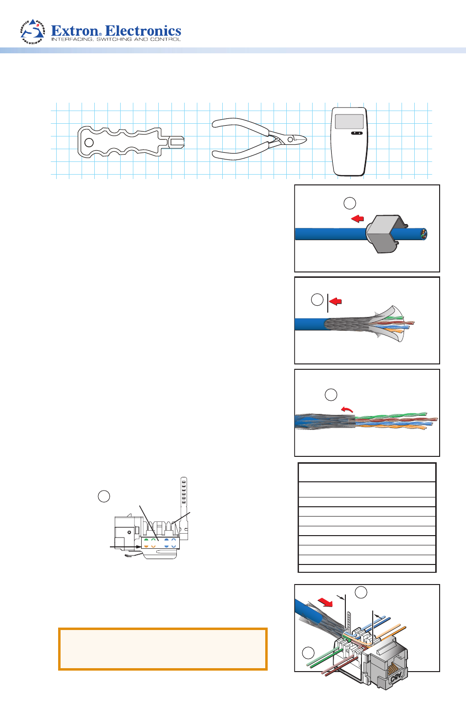
1.
Slide the rear case of the connector over the
cable. Push the case back at least 3 inches
(76 mm) to make room for the termination of the
cable.
2.
Remove about 2 inches (50 mm) of the cable
jacket.
3.
Fold down the braid over the cable jacket.
Remove the foil and mylar shielding (if present).
4.
Note the color codes and pin numbers on the
sides of the connector. Follow the color code in
the table at right to wire the connector.
5.
Untwist the wire pairs and hold the end of the
stripped cable jacket close to the back of the
connector. The length of the exposed wires in the
connector should not exceed 0.6 inch (see image
at right).
ATTENTION:
Failure to position the
cable properly may result in crosstalk and
improper termination.
Slide Rear Case
over Cable
1
Strip Jacket 2"
2
Strip Jacket 2"
Fold Braid over Jacket
and Remove Foil
3
4
Color-coded Label
w/ Pin Number
Color Code B
IDC Slots
2 1
4 5
A
B
5
6
Distance Between
Cable and Connector
0.6"
IDC
Position
T568B Wiring
IDC Numbers & Color Codes
White/
Blue
T568B
Wire Colors
5
4
1
2
3
6
7
8
Blue
White/
Orange
Orange
White/
Green
Green
White/
Brown
Brown
110-Style Punchdown Tool
(Provided)
Wire Cutter
RJ-45 Tester
6.
Position each wire into its respective IDC slot. Insert
the wires just far enough to hold them in the IDC slots.