Mounting the smb to a surface, Cable routing – Extron Electronics SMB 100 Series Installation User Manual
Page 2
SMB Series Surface Mount Boxes • Installation Guide (Continued)
Extron Headquarters
+800.633.9876 Inside USA/Canada Only
Extron USA - West
Extron USA - East
+1.714.491.1500 +1.919.850.1000
+1.714.491.1517 FAX
+1.919.850.1001 FAX
Extron Europe
+800.3987.6673
Inside Europe Only
+31.33.453.4040
+31.33.453.4050 FAX
Extron Asia
+800.7339.8766
Inside Asia Only
+65.6383.4400
+65.6383.4664 FAX
Extron Japan
+81.3.3511.7655
+81.3.3511.7656 FAX
Extron China
+4000.EXTRON
+4000.398766
Inside China Only
+86.21.3760.1568
+86.21.3760.1566 FAX
Extron Middle East
+971.4.2991800
+971.4.2991880 FAX
Extron Korea
+82.2.3444.1571
+82.2.3444.1575 FAX
Extron India
1800.3070.3777
Inside India Only
+91.80.3055.3777
+91.80.3055.3737
FAX
©
2012 Extron Electronics All rights reserved. All trademarks mentioned are the property of their respective owners.
www.extron.com
68-2302-01
Rev. A
08 12
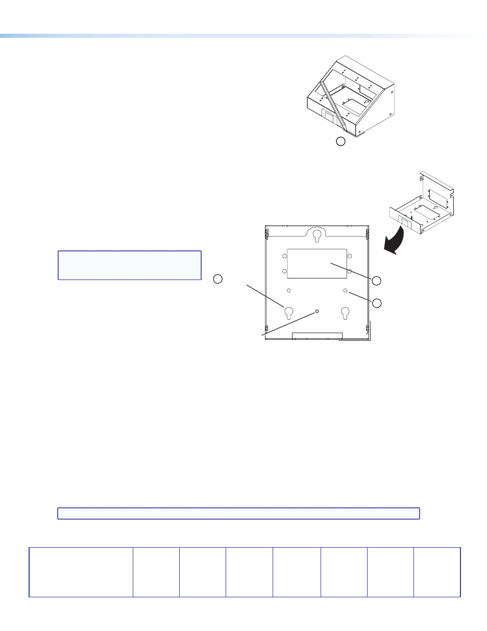
Mounting the SMB to a Surface
1.
Find a suitable location and use a non‑permanent marker or tape to outline
at least one corner of the SMB perimeter on the surface.
To access the rear keyhole slots or other mounting holes, it may be
necessary to remove the enclosure cover. To remove the cover, first remove
three screws on each side (six total), then lift the cover off.
Cable Routing
Cables may access the SMB through the AAP openings and through raceway knockouts.
1.
If cables enter the SMB through the rear panel, use the rear panel AAP openings. AAP modules are sold separately.
2.
With the SMB fastened to the mounting surface, run all necessary cables through the pass‑through opening before installing
any device(s) into the SMB.
NOTE: A nut is provided for grounding installed devices.
3.
Once the SMB is secured, cable the connections, then install the AAPs or other devices.
SMB 103
Three-gang SMB
(shown)
Mark location
of bottom plate.
1
2.
Using the bottom plate, mark the pilot hole
locations for the:
a.
three keyhole slots, or
b.
two mounting holes.
NOTE: Alternately, 1/4 inch bolts can be
used in the larger portion of the keyhole
slot. Mark the pilot holes accordingly.
3.
If required, mark the location for the cable
access hole.
4.
Drill 3/32 inch pilot holes for the keyhole slots
marked in step
2a or the mounting holes
marked in step
2b.
z
Cut cable access hole marked in step
3.
z
If using the smaller portion of the keyhole
slots, insert screws into the pilot holes, but
do not tighten until the bottom plate is slid into position.
5.
Mount the SMB bottom plate with the fasteners.
6.
If the cover was removed, replace it.
Grounding
Stud
Keyhole
Slots (3)
2
a
(Optional)
Mark Cable
Access Location
3
Mounting
Holes (2)
2
b
Bottom
Plate