Installation, Specifications, Connections, indicators, and controls – Extron Electronics P-2 DA2xi MT User Guide User Manual
Page 3
○
○
○
○○○○○○○○○○○○○○○○○○○○○○○○○○○○○○○○○○○○○○○○○○○○○○○○○○○○○○○○○○○○○○○○○○○○○○○○○○○○○○○○○○○○○○○○○○○○○○○○○○○○○○○○○○○○○○○○○○○○○○○○○○○○
○○○○○○○○○○○○○○○○○○○○○○○○○○○○
○
○
○
○
○
○
○
○
○
○
○
○
○
○
○
○
○
○
○
○
○
○
○
○
○
○
○
○
○
○
○
○
○
○
○
○
○
○
○
○
○
○
○
○
○
○
○
○
○
○
○
○
○
○
○
○
○
○
○
○
○
○
○
○
○
○
○
○
○
○
○
○
○
○
○
○
○
○
○
○
○
○
○
○
○
○
○
○
○
○
○
○
○
○
○
○
○
○
○
P/2 DA2xi and P/2 DA2xi MT • Connections
P/2 DA2xi and P/2 DA2xi MT • Connections
Installation
5
4
P/2 DA2xi and P/2 DA2xi MT • Specifications
P/2 DA2xi and P/2 DA2xi MT • Specifications
Specifications
7
6
2
.
If feet were previously installed on the bottom of the unit,
remove them.
3
.
For furniture mounting,
hold the unit with the attached
brackets against the underside of the table or other
furniture. Mark the location of the screw holes of the
bracket on the mounting surface.
4
.
For furniture mounting,
drill 3/32” (2 mm) diameter pilot
holes, 1/4” (6.3 mm) deep in the mounting surface at the
marked screw locations.
5
.
For furniture mounting,
insert #8 wood screws into the four
pilot holes. Tighten each screw into the mounting surface
until just less than 1/4” of the screw head protrudes.
6
.
For furniture mounting,
align the mounting screws with
the slots in the brackets and place the unit against the
surface, with the screws through the bracket slots.
7
.
For furniture mounting,
slide the receiver slightly forward or
back, then tighten all four screws to secure the unit in place.
8
.
For projector mounting,
secure the unit to a projector
mount or other surface by inserting the mounting bolt
through the bracket’s slotted hole.
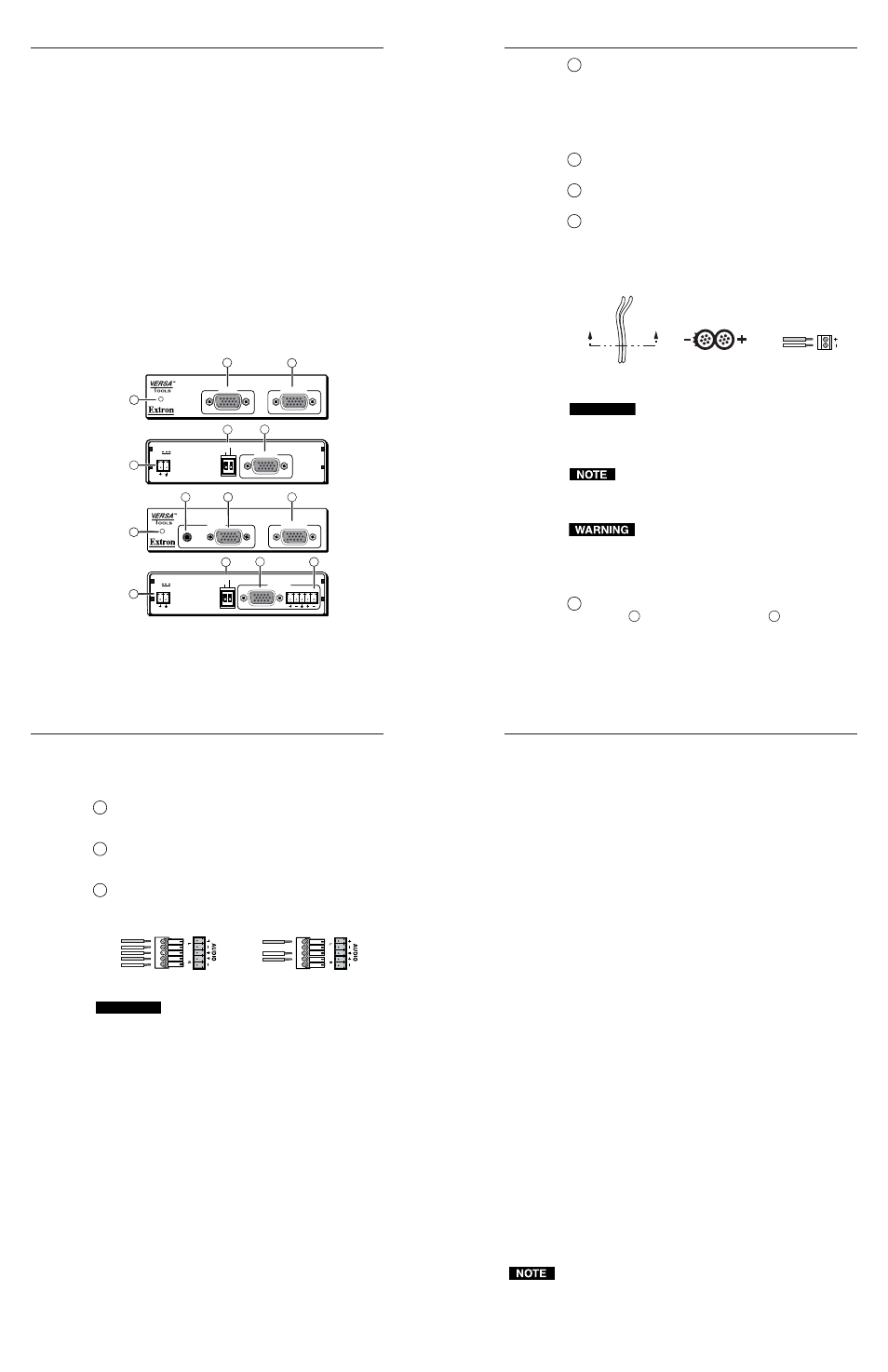
Connections, Indicators, and Controls.
Figure 4 — P/2 DA2xi and P/2 DA2xi front and rear
panels
1
Power/Signal indicator LED
— When illuminated green,
this LED indicates that the distribution amplifier is
receiving both power and a computer signal. When
illuminated amber, it indicates that the distribution
amplifier is receiving power but no computer signal. If the
LED is off when the distribution amplifier is connected to a
PC with power on, it indicates that an external power
supply is required.
2
Video Input connector
— Connect a computer’s VGA -
UXGA output to this connector.
3
Monitor connector
— Connect a local monitor to this
connector.
4
Power connector —
Plug the external 12V power supply
only when needed
(see Power/Signal indicator LED above)
into this 2-pole captive screw connector. The power supply
is included with the unit and is shipped with a plug
installed. If you need to cut the power cord to a different
length and reinstall the plug, refer to figure 5 and the
following notes.
Figure 5 — Power connector wiring
CAUTION
When connecting the power supply, voltage polarity
is extremely important. Applying power with
incorrect voltage polarity could damage the power
supply and the P/2 DA2xi. Identify the power cord
negative lead by the ridges on the side of the cord.
Do not tin the stripped power supply leads before
installing the captive screw connector. Tinned wires are
not as secure in the captive screw connectors and could
pull out.
The two power cord wires must be kept separate
while the power supply is plugged in. Remove
power before continuing.
To verify the polarity before connection, plug in the power
supply with no load and check the output with a voltmeter.
5
2-bank DIP switch
— (These switches only affect the video
output (
6
), not the “monitor” output (
3
)). The Gain/
Peak
DIP switch should be on (up) when output cable is
over 100’ (30.5 m). The Out Imp DIP switch changes
output impedance. If all connections and operations are
correct, yet the projector has no picture, switch to the other
position.
6
Video output connector
— Connect the video output
device, such as a projector, LCD panel, or monitor, to this
connector.
7
Audio input
connector (MT model only) — Plug a
3.5 mm, mini jack audio cable from the computer’s sound
card into this connector.
8
Audio output
connector (MT model only) — Insert a
3.5 mm, 5-pole, captive screw audio connector into this
connector. Wire the connector as shown below.
Figure 6 — Audio connector wiring
CAUTION
Connect the sleeve to ground (Gnd). Connecting the
sleeve to a negative (-) terminal will damage the
audio output circuits.
Specifications
Video
Gain ................................................... Selectable: unity (0.7V) or 100% (0.75V)
Peaking ............................................. Selectable: 0dB or 6dB @ 100 MHz
Bandwidth ........................................ 350 MHz (-3dB)
Video input
Number/signal type ...................... 1 VGA-UXGA RGBHV, RGBS, RGsB, RsGsBs
Connectors ....................................... (1) 15-pin HD male
Nominal level .................................. 0.7V p-p for RGB
Minimum/maximum levels ......... Analog, 0.3V to 1.5V p-p
Impedance ........................................ 75 ohms
Horizontal frequency ..................... 15 kHz to 135 kHz
Vertical frequency ........................... 30 Hz to 170 Hz
Return loss ........................................ <-38dB @ 5 MHz
Maximum DC offset ....................... 1.0V
AC/DC coupling ............................ No
Video output
Number/signal type ...................... 1 VGA-UXGA RGBHV, RGBS, RGsB, RsGsBs
output
1 VGA-UXGA RGBHV, RGBS, RGsB, RsGsBs
local monitor loop-through (ID bits are passed)
Connectors ....................................... (2) 15-pin HD female
Nominal level .................................. 0.7V p-p for RGB
Minimum/maximum levels ......... Analog, 0.3V to 1.5V p-p
Impedance ........................................ 75 ohms
Return loss ........................................ <-40dB @ 5 MHz
DC offset ........................................... ±5mV maximum with input at 0 offset
Sync
Input type ......................................... RGBHV, RGBS, RGsB, RsGsBs
Output type ...................................... RGBHV, RGBS, RGsB, RsGsBs
Min/Max Input level ..................... 1.5V to 5.0V p-p
Output level ..................................... TTL, 5.0V p-p (when not terminated)
Input impedance ............................. 510 ohms
Output impedance .......................... 75 ohms or 50 ohms switchable
Max. propagation delay ................. 60 ns
Max. rise/fall time .......................... 4 ns
Polarity .............................................. Positive or negative (follows input)
Audio (P/2 DA2xi MT only)
Gain ................................................... Unbalanced 0dB, balanced +6dB
Frequency Response ....................... 20Hz to 20kHz, ±0.05dB
THD + Noise .................................... <0.03% @ 1kHz at nominal level
S/N .................................................... >90dB, balanced at rated max output drive
Crosstalk ........................................... <-80dB @ 1kHz, fully loaded
Stereo channel separation .............. >80dB @ 1kHz; >60dB @ 20kHz
CMRR ................................................ >75dB @ 20Hz to 20kHz
Audio input (P/2 DA2xi MT only)
Number/signal type ...................... 1 stereo, unbalanced
Connectors ....................................... (1) 3.5 mm female stereo jack, 2-channel; tip
(L), ring (R), sleeve (Gnd)
Impedance ........................................ >5 kohms unbalanced, DC coupled
Nominal level .................................. -10dBV (316mV)
Maximum level ............................... >+10dBV (3.16V) at 1% THD + N
Audio output (P/2 DA2xi MT only)
Number/signal type ...................... 1 stereo, balanced/unbalanced
Connectors ....................................... (1) 5-pin 3.5 mm captive screw connector
Impedance ........................................ 50 ohms unbalanced, 100 ohms balanced
Gain error .......................................... ±0.1dB channel to channel
Nominal level .................................. -2dBu (632mV) balanced out
-10dBV (316mV) unbalanced out
Maximum level (Hi-Z) ................... >+18dBu (6.32V), balanced at 1% THD+N
Maximum level (600 ohms) ........... >+12dBm (3.16V), balanced at 1% THD+N
0dBu = 0.775 volts 0dBv = 1.0 volts
INPUT
MONITOR
P/2 DA2xi
OUTPUT
1
ON
2
EXT POWER (see manual)
5V
0.1A MAX
GAIN/PEAK
OUT IMP
AUDIO
INPUT
MONITOR
L
R
P/2 DA2xi MT
OUTPUT
1
ON
2
EXT POWER (see manual)
5V
0.2A MAX
GAIN/PEAK
OUT IMP
7
6
1
2
6
3
5
6
6
7
6
1
2
3
7
4
6
5
6
6
7
6
8
4
Power Supply Output cord
End view of power
supply output cord
Captive screw
connector
A
A
SECTION A–A
+
–
12VDC
P
o
wer
Unbalanced Output
Tip
See Caution
Sleeve (s)
Tip
See Caution
Balanced Output
Tip
Ring
Sleeve (s)
Tip
Ring