P/2 da2xi p/2 da2xi mt, User’s guide, Introduction – Extron Electronics P-2 DA2xi MT User Guide User Manual
Page 2: Fcc class a notice
○
○
○
○
○○○○○○○○○○○○○○○○○○○○○○○○○○○○○○○○○○○○○○○○○○○○○○○○○○○○○○○○○○○○○○○○○○○○○○○○○○○○○○○○○○○○○○○○○○○○○○○○○○○○○○○○○○○○○○○○○○○○○○○○○○○
○○○○○○○○○○○○○○○○○○○○○○○○○○○○
User’s
Guide
P/2 DA2xi and P/2 DA2xi MT • Installation
P/2 DA2xi and P/2 DA2xi MT • Installation
Introduction
3
2
○
○
○
○
○
○
○
○
○
○
○
○
○
○
○
○
○
○
○
○
○
○
○
○
○
○
○
○
○
○
○
○
○
○
○
○
○
○
○
○
○
○
○
○
○
○
○
○
○
○
○
○
○
○
○
○
○
○
○
○
○
○
○
○
○
○
○
○
○
○
○
○
○
○
○
○
○
○
○
○
○
○
○
○
○
○
○
○
○
○
○
○
○
○
○
○
○
○
○
○
© 2003 Extron Electronics.
All rights reserved.
Extron Electronics, USA
1230 South Le
wis Str
eet
Anaheim, CA 92805
USA
714.491.1500
Fax 714.491.1517
Extron Electronics, Europe
Beeldschermw
eg 6C
3821 AH Amersfoort
The Netherlands
+31.33.453.4040
Fax +31.33.453.4050
Extron Electronics, Asia
135 Joo S
eng Road, #04-01
PM Industrial B
uilding
Singapor
e 368363
+65.6383.4400
Fax +65.6383.4664
Extron Electronics, Japan
Daisan DMJ B
uilding 6F
3-9-1 Kudan M
inami
Chiyoda-ku,
T oky
o 102-0074 Japan
+81.3.3511.7655
Fax +81.3.3511.7656
www.extron.com
Distribution Amplifiers
68-713-01 Rev
. A
Printed in the USA
01 03
P/2 DA2xi
P/2 DA2xi MT
The P/2 DA2xi and the P/2 DA2xi MT are distribution amplifiers
that accept video input from a VGA, XGA, or UXGA compatible
PC and distribute the signal to separately buffered outputs. Each
output can be extended with Extron VGA-Mini-HR cables from 6'
to 250' in length. The MT model also has audio input and output.
Both models can be powered by newer computers compatible
with the new VESA standard using pin 9 of the VGA connector as
the +5VDC source. An external power supply is also provided
for use with older computers, where power is unavailable
through the VGA connector, or the available power is inadequate.
Features
• Powered by computer —
This unit can be powered by most
newer computers.
• Power/Signal LED —
Green LED = power + signal. Amber
LED = Power but no signal. Off = no power.
• Gain/Peak DIP switch —
To compensate for longer cable runs.
Switch to on (up) when output cable is over 100’ (30.5 m).
• Out Imp DIP switch —
Changes the output impedance to be
compatible with all projectors.
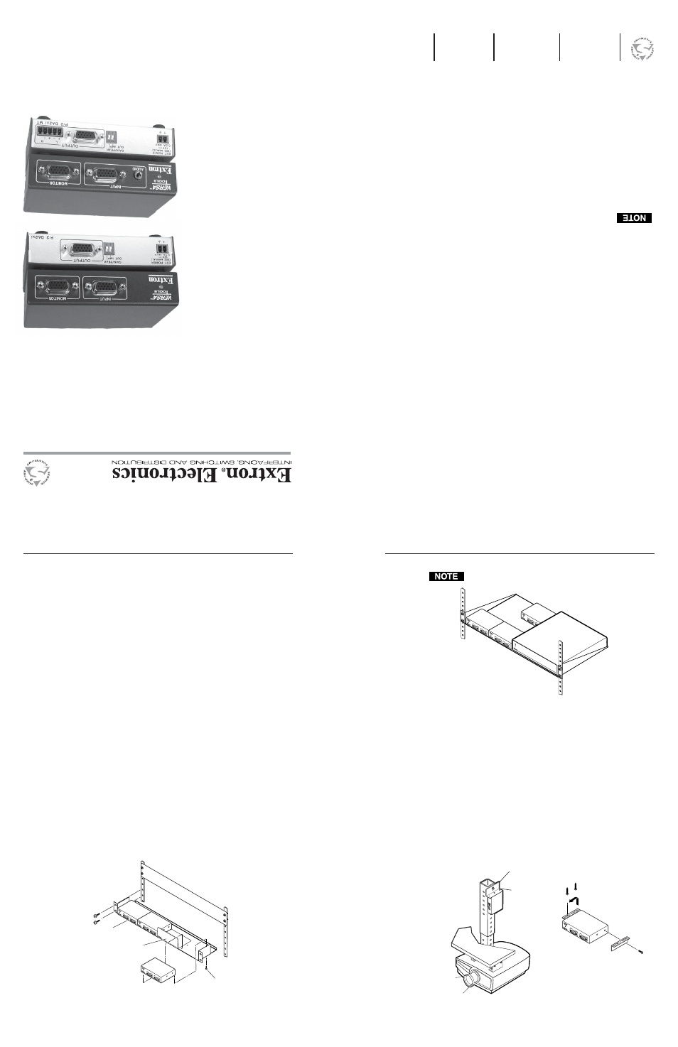
Installation
The P/2 DA2xi and P/2 DA2xi MT can be mounted on a rack
shelf, under a desk or tabletop, or on a projector bracket.
Rack mounting
For optional rack mounting, mount the P/2 DA2xi or P/2 DA2xi
on a VersaTools 19" 1U Rack Shelf (part #60-190-20) or a standard
Universal 1U Rack Shelf (part #60-190-01) as shown in figures 1
and 2, respectively.
Figure 1 — Rack mounting the P/2 DA2xi and
P/2 DA2xi MT on the VersaTools rack shelf
Only products in the VersaTools line can be mounted to a
VersaTools rack shelf.
Figure 2 — Mounting the P/2 DA2xi and P/2 DA2xi MT
on the standard rack shelf
1
.
Remove the rubber feet (if installed) and mount the unit on the
rack shelf, using two screws in opposite (diagonal) corners.
2
.
Install blank panel(s) or other unit(s) to the rack shelf.
3.
Insert the shelf into the rack, and secure the shelf to the rack
using the supplied machine screws.
Furniture or projector mounting
Furniture mount or projector mount the unit using the optional
mounting kit (part #70-077-01, furniture, or #70-077-04, projector)
as follows:
1
.
Attach the mounting brackets to the P/2 DA2xi or
P/2 DA2xi MT with the provided machine screws (figure 3).
Figure 3 — Desk and projector mounting the
P/2 DA2xi or P/2 DA2xi MT
FCC Class A Notice
Note: This equipment has been tested and found to comply with the limits for a
Class A digital device, pursuant to part 15 of the FCC Rules. These limits are designed
to provide reasonable protection against harmful interference when the equipment is
operated in a commercial environment. This equipment generates, uses and can
radiate radio frequency energy and, if not installed and used in accordance with the
instruction manual, may cause harmful interference to radio communications.
Operation of this equipment in a residential area is likely to cause harmful
interference, in which case the user will be required to correct the interference at his
own expense.
Note: This unit was tested with shielded cables on the peripheral devices. Shielded
cables must be used with the unit to ensure compliance.
General
Power................................................
+5VDC from pin 9 of the VGA input
connector.
Or
..........................................
100VAC to 240VAC, 50/60 Hz, 5 watt,
external, autoswitchable; to 12VDC, 1A
power supply. P2 DA2xi requires 0.1A, and
P2 DA2xi MT requires 0.2A.
Temperature/humidity.................
Storage -40° to +158°F (-40° to +70°C) / 10%
to 90%, non-condensing
Operating +32° to +122°F (0° to +50°C) / 10%
to 90%, non-condensing
Rack mount......................................
Yes, with optional 1U VersaTools rack shelf,
part #60-190-20 or Universal rack shelf, part
#60-190-01
Enclosure type..
...............................
Metal
Enclosure dimensions....................
1" H x 4.3" W x 3" D
2.5 cm H x 10.9 cm W x 7.6 cm D
(Depth excludes connectors.)
Product weight................................
0.5 lbs (0.3 kg)
Shipping weight..............................
3 lbs (1.4 kg)
Vibration...........................................
ISTA/NSTA 1A in carton (International Safe
Transit Association)
Listings..............................................
UL, CUL
Compliances....................................
CE, FCC Class A, VCCI, AS/NZS, ICES
MTBF.................................................
30,000 hours
Warranty...........................................
3 years parts and labor
Specifications are subject to change without notice.
INPUT
MONIT
OR
IN
PUT
MO
NI
TOR
INPUT
MONI
TO
R
MDA SER
IES
DISTR
IBU
TION
AM
PLIF
IER
Ceiling
Digital Projector
Projector
Mounting
Bracket
Mounting
Bolt
INP
UT
MON
ITO
R
P/2 D
A2xi
OUTPUT
GAIN/
PEAK
1
ON
2
SP
ARE
EXT PO
WER (see man
ual)
5V
0.1A MAX
IN
PU
T
MO
NIT
OR
INP
UT
MO
NIT
OR
INP
UT
MO
NIT
OR
VersaTools Rack Shelf
1/4 Rack Width False
Front Face Plate
Use 2 mounting holes
on opposite corners.
(2) 4-40 x 3/16" screws