Extron Electronics MTP T 15HD A Setup Guide User Manual
Mtp t 15hd a architectural series • setup guide, Pre-installation — device location preparation, Installation
IMPO
RTAN
T:
Go to www
.extron.com f
or the complete
user guide
, installation instructions,
and
specifications bef
ore connecting the
product to the po
wer sour
ce.
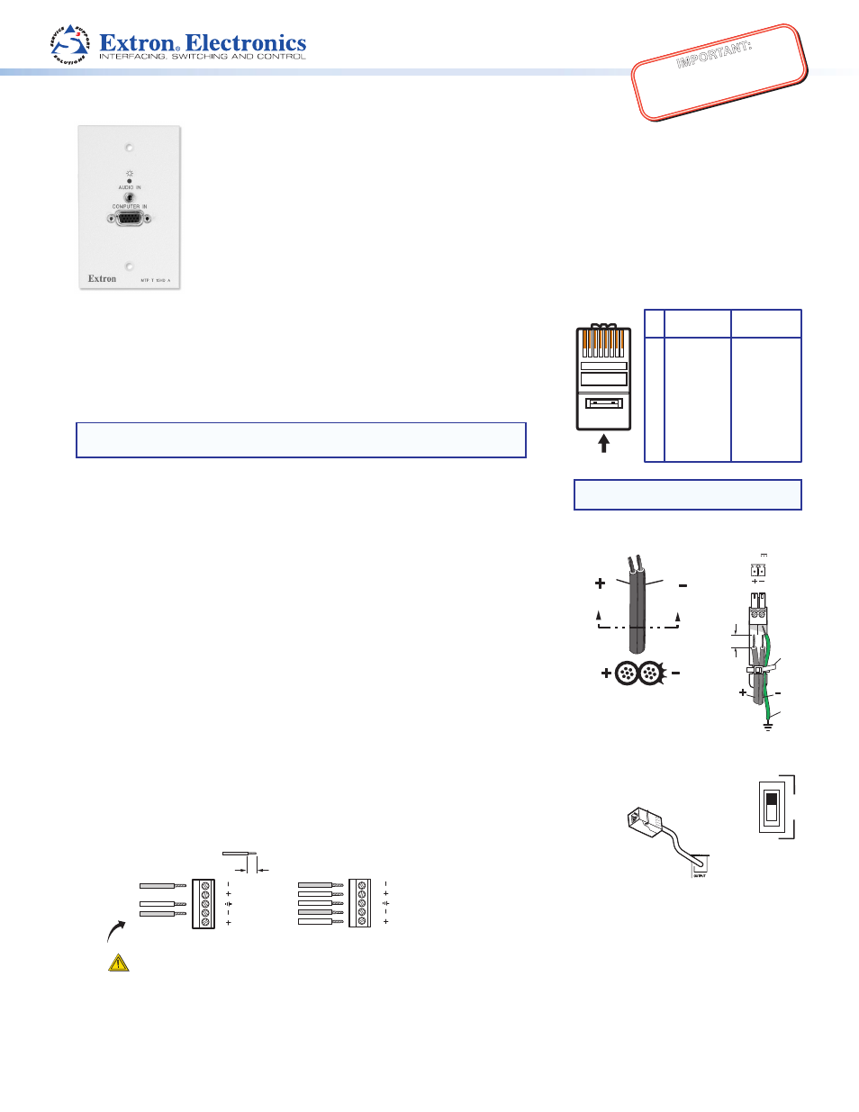
MTP T 15HD A Architectural Series • Setup Guide
This card provides basic instructions for an experienced installer to set up and operate the Extron MTP T 15HD A
Architectural Series products; the MTP T 15HD WM, MTP T 15HD D, and MTP T 15HD AAP models.
See the MTP T 15HD A Architectural Twisted Pair Transmitters User’s Guide (at
wwww.extron.com
)
for detailed information.
Pre-installation — Device Location Preparation
12345678
Insert Twisted
Pair Wires
Pins:
NOTE: If you are using Enhanced Skew-Free™
A/V cable, use the TIA/EIA T568A standard only.
Pin
1
2
3
4
5
6
7
8
T568A
Wire Color
White-green
Green
White-orange
Blue
White-blue
Orange
White-brown
Brown
T568B
Wire Color
White-orange
Orange
White-green
Blue
White-blue
Green
White-brown
Brown
The MTP T 15HD A WM and D models can be installed in 1-gang electrical wall boxes, and
the MTP T 15HD A AAP can be attached to a device faceplate or an AAP wall plate. See the
MTP T 15HD A Architectural Twisted Pair Transmitters User’s Guide, for method of installing
the electrical box or wall plate.
Run video and audio output cables from the output device locations to the MTP T 15HD
location ready for the final installation of the device.
NOTE:
Terminate TP output cables as shown on the right, using the same standard
(A or B) at both ends.
Run the 12 VDC power supply to the MTP T 15HD location.
Installation
Step 1 — Cabling and Mounting
Turn off or disconnect all equipment power sources.
Power Supply
Output Cord
SECTION A–A
Ridges
Smooth
A
A
Tie
Wrap
POWER
12V
xA MAX
Rear
Panel
Ridges
Earth
Ground
3/16"
(5 mm)
Max.
1.
Power — Plug the 12 VDC power supply into the rear panel, direct insertion, 3.5 mm,
2-pole captive screw connector. Wire the connector as shown.
Grounding the Power Input Port
Extron MTP products can be adversely affected by electrostatic discharge (ESD) if they are
not grounded correctly.
To prevent malfunctions or product damage, an experienced installer can correctly ground
an Extron MTP product by inserting one end of the grounding wire to the negative or ground
pin on the power input connector (see the image on the right). Tie the other end of the wire
to an earth ground.
Plug the connector into the MTP .
If you have any questions about how to ground a product in a specific application, contact an Extron technical support specialist.
2.
Pre-peaking — Set the pre-peaking switch on the rear panel for long cable runs as desired. See the switch settings table on
ON
OFF
PRE-
PEAK
the next side, or see the online MTP T 15HD A Architectural Twisted Pair Transmitters User’s Guide.
3.
Output cabling — Connect the TP cable to the rear panel RJ-45 connector.
4.
Audio cabling — For stereo output, insert bared audio cable into the 3.5 mm, 5-pole direct
insertion captive connector, as shown below.
Unbalanced Stereo Output
Balanced Stereo Output
CAUTION
For unbalanced audio, connect the sleeve(s) to the center contact
ground.
DO NOT
connect the sleeve(s) to the negative (-) contacts.
Tip
See Caution
Sleeve (s)
Tip
See Caution
Tip
Ring
Sleeve (s)
Tip
Ring
L
R
AUDIO
L
R
AUDIO
0.2” (5 mm) max.
Do not tin the wires!