Front panel switch settings and leds, Final installation, Grounding the power input port – Extron Electronics MTP U T A D Setup Guide User Manual
Page 2
68-1674-50 Rev. D
01 13
MTP U T A D • Setup Guide
Extron Headquarters
+800.633.9876 Inside USA/Canada Only
Extron USA - West
Extron USA - East
+1.714.491.1500 +1.919.850.1000
+1.714.491.1517 FAX
+1.919.850.1001 FAX
Extron Europe
+800.3987.6673
Inside Europe Only
+31.33.453.4040
+31.33.453.4050 FAX
Extron Asia
+800.7339.8766
Inside Asia Only
+65.6383.4400
+65.6383.4664 FAX
Extron Japan
+81.3.3511.7655
+81.3.3511.7656 FAX
Extron China
+4000.EXTRON
+4000.398766
Inside China Only
+86.21.3760.1568
+86.21.3760.1566 FAX
Extron Middle East
+971.4.299.1800
+971.4.299.1880 FAX
Extron Korea
+82.2.3444.1571
+82.2.3444.1575 FAX
Extron India
1800.3070.3777
Inside India Only
+91.80.3055.3777
+91.80.3055.3737 FAX
©
2013 Extron Electronics All rights reserved. All trademarks mentioned are the property of their respective owners.
www.extron.com
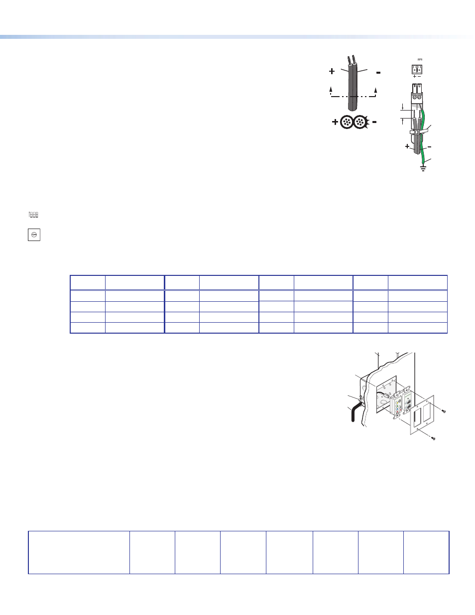
Grounding the Power Input Port
Power Supply
Output Cord
SECTION A–A
Ridges
Smooth
A
A
POWER
12V
xA MAX
Tie
Wrap
Rear
Panel
Ridges
Earth
Ground
3/16"
(5 mm)
Max.
Extron MTP U T A D transmitters can be adversely affected by electrostatic discharge (ESD)
if they are not grounded correctly.
To prevent malfunctions or product damage, an experienced installer can correctly ground
an Extron MTP U T A D transmitter product by inserting one end of the grounding wire to the
negative or ground pin on the power input connector (see the image on the right). Tie the
other end of the wire to an earth ground.
Plug the connector into the MTP U T A D transmitter.
If you have any questions about how to ground a product in a specific application, contact an
Extron technical support specialist.
Front Panel Switch Settings and LEDs
•
DIP Switches
•
Contact — Set this switch on (up) for contact closure control of the input selection. Set the switch off (down) for auto switch mode (the
transmitter automatically selects the highest format video input with a sync signal present).
•
Pre-Peak — View the image and set the Pre-Peaking switch for the best image quality to correct for long cable runs of the entire sytem
•
50 Hz Refresh — Set this switch on (up) for a 50 Hz refresh rate for the resolution selected by the EDID Select switch. Set this switch
off (down) for 60 Hz.
•
EDID Select rotary switch — Set this switch to one of the positions below to select either the local monitor as the source of the EDID data
or a specific resolution.
•
Position 0 — The loop-through monitor (2, on the other side of this guide) is the source of the EDID data.
•
Position 1 - F — Specify a resolution. The table below identifies the switch positions and the associated resolutions. By default, the
vertical refresh rate for all resolutions is 60 Hz. The resolution can be set to 50 Hz using the Refresh DIP switch.
Position
Source or
Resolution
Position
Resolution
Position
Resolution
Position
Resolution
0
Local monitor
4
1280 x 768
8
1366 x 768
C
1680 x 1050
1
800 x 600
5
1280 x 800
9
1400 x 1050
D
1920 x 1080
2
1024 x 768
6
1280 x 1024
A
1440 x 900
E
1920 x 1200
3
1280 x 720
7
1360 x 768
B
1600 x 1200
F
Not used
•
LEDs —
•
Power — This LED indicates power is applied to the MTP.
Decora
Faceplate
Wall opening
is flush with
edge of box.
Installation
Cable
Cable Clamp
Wall Stud
45
1
2
0
E
87
6
3
9
A
D
BC
F
DDC
RESOL.
SWITCH MODE
PRE-PEAK
REFRESH 50/60H
z
ON
1
2
3
AUDIO INPU
T
CO
MPU
TER IN
PU
T
MONITOR OU
T
PW
R
VID
Y/C
YU
V R
GB
INPUTS
VIDE
O
S-VIDE
O
AUDI
O
L
R
Pr
Pb
Y
YU
V
MTP U T A D
Transmitter
•
Active input — The lit LED: PC, YUV, S-VID, or Vid; indicates the video input connector
that is selected for transmission.
Final Installation
1.
Make all connections, test the system, and install the device when operation is satisfactory.
2.
At the power outlet, unplug the power supply.
3.
Mount the transmitter into the wall box, and attach the supplied Decora faceplate to the unit.
4.
At the power outlet, reconnect the power supply.
45
12
0
E
87
6
3
9
A
D
BC
F
EDID
SELECT
CON
TA
CT
PRE-PEAK
50 Hz REFRES
H
ON
1 2 3