Extron Electronics MTP U T A D Setup Guide User Manual
Preparing the mounting surface, Front panel inputs, Rear panel connections
IMPO
RTAN
T:
Go to www
.extron.com f
or the complete
user guide
, installation instructions,
and
specifications bef
ore connecting the
product to the po
wer sour
ce.
MTP U T A D • Setup Guide
This guide provides quick start instructions for an experienced installer to set up and operate an Extron MTP U T A D universal transmitter.
Preparing the Mounting Surface
NOTE: Use a wall box with a depth of at least 2.5 inches (6.4 cm).
1.
Place the wall box against the installation surface and mark the opening guidelines.
TIP: Use a level to properly orient the opening.
2.
Cut out the material from the marked area.
3.
Secure the wall box with 10-penny nails or #8 or #10 screws, leaving the front edge flush with the outer wall or furniture surface.
4.
Run all required cables (see Rear Panel Connections) and secure them with cable clamps.
Front Panel Inputs
45
12
0
E
87
6
3
9
A
D
BC
F
INPUTS
VIDEO
AUDIO INPUT
COMPUTER INPUT
MONITOR OUT
S-VIDEO
PWR VID S-VID YUV PC
AUDIO
L
EDID SELECT
CONT
ACT
PRE-PEAK
50Hz REFRESH
R
Pr
Pb
Y
YUV
ON
1 2 3
1 2 3 4
12V
.5A MAX
OUTPUT
Side
2
1
7
6
3
4
5
8
9
10
a
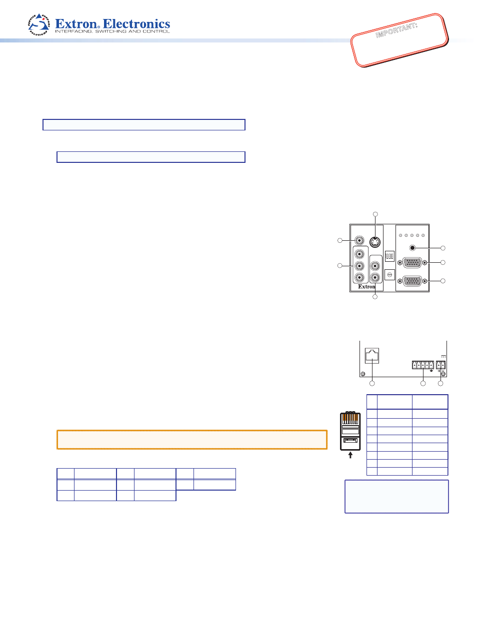
Plug a computer (VGA) video source into the Computer Input 15-pin HD connector.
b
Plug a VGA monitor into the Monitor Out 15-pin HD connector.
c
Plug a high definition or standard definition component video source into the YUV RCA
connectors.
d
Plug a composite video source into the Video RCA connector.
e
Plug an S-video source into the S-video 4-pin mini-DIN connector.
f
Plug a stereo audio source into the audio RCA connectors.
g
Plug a stereo audio source into the 3.5 mm mini jack connector.
Rear Panel Connections
45
12
0
E
87
6
3
9
A
D
BC
F
INPUTS
VIDEO
AUDIO INPUT
COMPUTER INPUT
MONITOR OUT
S-VIDEO
PWR VID S-VID YUV PC
AUDIO
L
EDID SELECT
CONT
ACT
PRE-PEAK
50Hz REFRESH
R
Pr
Pb
Y
YUV
ON
1 2 3
1 2 3 4
12V
.5A MAX
OUTPUT
Side
2
1
7
6
3
4
5
8
9
10
h
Terminate a TP cable as shown below at right. Connect it between the transmitter Output port
and the receiver Input port (both ends need to match).
i
Wire the 5-pole captive screw connector for the contact closure control of input selections
as shown below. To select a video input as the transmitter output, momentarily tie the
Pin
1
2
3
4
5
6
7
8
Wire color
White-green
Green
White-orange
Blue
White-blue
Orange
White-brown
Brown
Wire color
T568A
T568B
White-orange
Orange
White-green
Blue
White-blue
Green
White-brown
Brown
12345678
Insert Twisted
Pair Wires
Pins:
assigned pin for that format to ground.
j
Wire the 2-pole captive screw connector for the included external 12 VDC, 1 A power supply
(see image and grounding instructions on the next page).
ATTENTION:
Do not connect these devices to a computer or telecommunications
network.
Contact closure input selection connector wiring:
Pin
Format
Pin
Format
Pin
Ground
1
Composite
3
YUV
5
Ground
2
S-video
4
PC
NOTE: If you are using an
Enhanced Skew-Free™ A/V
cable, use the TIA/EIA T568A
standard only.