Installation and operation, Introduction, Installation – Extron Electronics KP 6 Keypad Remote User Manual
Page 2: 60hz, Installation with a 9-pin d-sub connector, Installation with a captive screw connector
Keypad Remote Controls • Installation and Operation
Keypad Remote Controls • Installation and Operation
Installation and Operation
3
2
Introduction
The KP 6 is designed to control MSW 4 Series, SW AV Series (4 and 6
input models only), SW VGA/Ars Series, and SW RGBHV/ A Series
switchers, or other Extron products with contact closure ports or
ports labeled as “Remote.”
The KP 6 is a contact closure remote for selecting the switcher’s input.
When a number key is pressed, the wire associated with that input is
momentarily shorted to ground, making the switcher switch to that
input.
The KP 6 can control up to 6 inputs and requires no power.
Installation
Installation with a 9-pin D-sub connector
Many switchers, such as the SW6 VGA Ars Switcher, come equipped
with a 9-pin D-sub connector. To use the KP 6 Keypad Remote
Control on this type of switcher, install it as follows:
1
.
Power down the switcher.
2
.
Connect the KP 6 adapter’s 9-pin plug to the contact closure
connector on the switcher’s rear panel.
3
.
Position the KP 6 Keypad for the most convenient operation.
4
.
Power up the switcher.
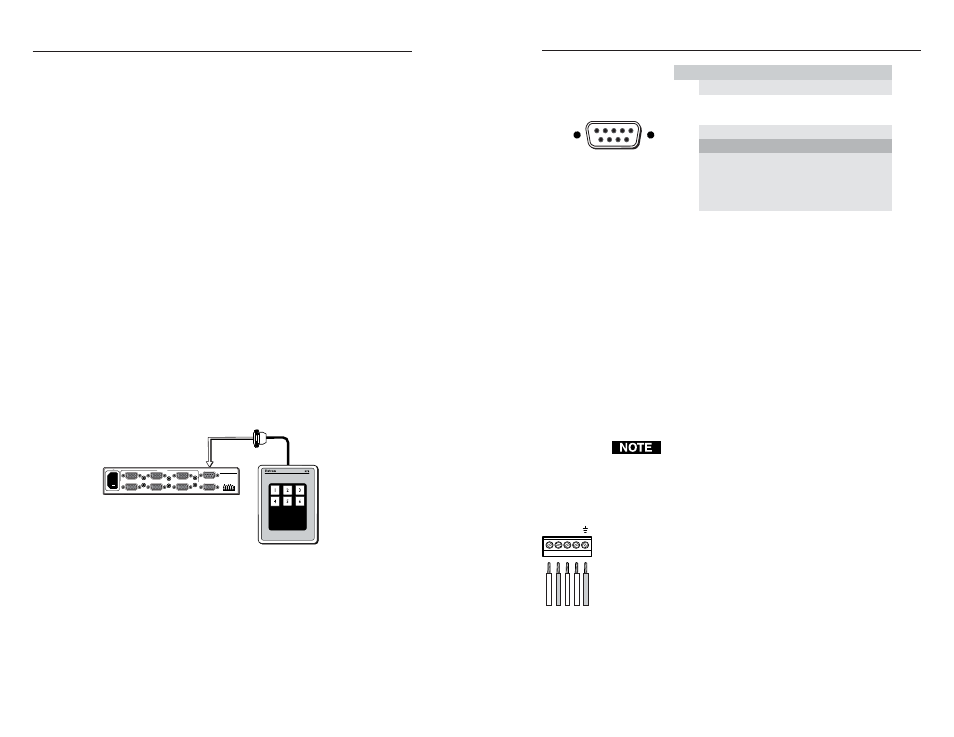
Figure 1 — Typical KP 6 application (with 9-pin D-
sub connector)
Figure 2 — 9-pin Sub-D connector pinout
Installation with a captive screw connector
Some switchers, such as the MSW 4 Series, are not equipped with
9-pin D-sub connectors and have a 3.5mm, 5-pole captive screw
connector (labeled “Contact”) instead. In order to use the KP 6
Keypad Remote Control with these switchers, a captive screw
connector (included with the switcher) must be used. To use a captive
screw connector, the existing 9-pin D-sub connector must be removed
from the cable and a captive screw connector installed.
To install the captive screw connector, remove the wire from the 9-pin
D-sub connector, then strip the wires and insert them into the new
connector (supplied with the switcher). Wire the connector as shown
here. Tighten the screws to secure the wires. Clip off the green and
blue wires.
Do not tin the stripped wire leads before installing the
captive screw connector. Tinned wires are not as secure
in the captive screw connectors and could pull out.
Install the KP 6 Keypad Remote Control on this type of switcher as
follows:
1
.
Rewire the connector on the KP 6 Keypad Remote Control.
2
.
Power down the switcher.
3
.
Connect the KP 6 adapter’s captive screw connector to the
“Contact” connector on the switcher’s rear panel.
4
.
Position the KP 6 Keypad for the most convenient operation.
5
.
Power up the switcher.
Bro
wn
Red
Or
ange
Y
ello
w
Blac
k
4
3
2
1
25 foot
cable
KP 6 Keypad
Remote Control
SW6 VGA Ars Switcher
SW6 VGA Ars
REMOTE
100-240V 0.2A
INPUTS
1
2
3
4
5
50-60Hz
OUTPUT
OUTPUT
L
R
SW6 VGA Ars
6
n
i
P
e
r
u
s
o
l
c
t
c
a
t
n
o
C
n Wire color
o
i
t
c
n
u
F
1
1
#
n
I
1 Brown
#
t
u
p
n
I
2
3
4
2
#
n
I
2 Red
#
t
u
p
n
I
5
d
n
G
d Black
n
u
o
r
g
l
a
n
g
i
S
6
3
#
n
I
3 Orange
#
t
u
p
n
I
7
4
#
n
I
4 Yellow
#
t
u
p
n
I
8
5
#
n
I
5 Green
#
t
u
p
n
I
9
6
#
n
I
6 Blue
#
t
u
p
n
I
Not used
—
Not used
—
Male
1
5
6
9
—
—