Transmitter and receiver throughput connections, Transmitter and receiver throughput, Connections – Extron Electronics MTP AV Series User Guide User Manual
Page 15: Mtp av series • installation 9
MTP AV Series • Installation
9
Transmitter and Receiver Throughput Connections
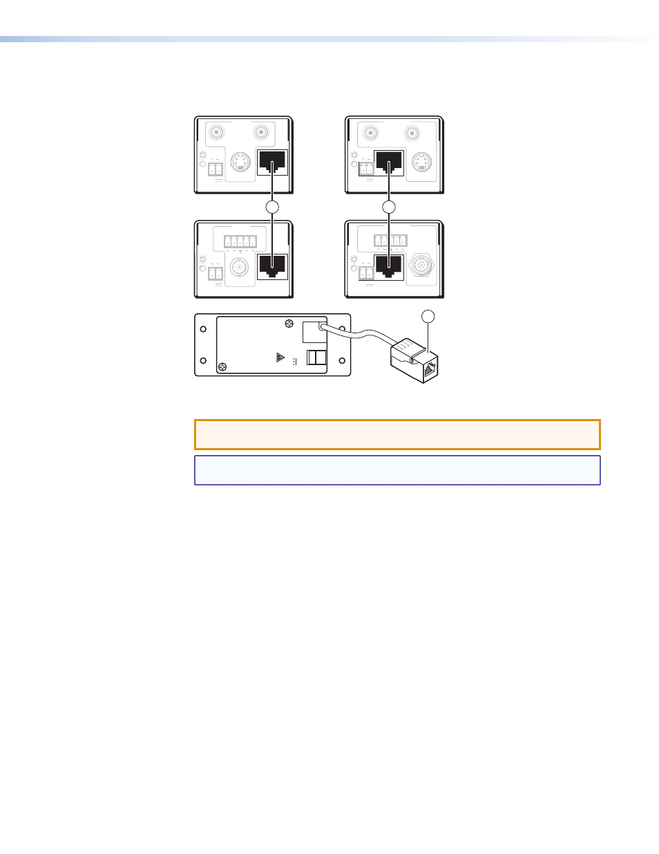
12 identifies the connections between the transmitter and receiver.
12V
0.5A
MAX
OUTPUT
PO
WER − +
MTP Transmitters
MTP Receivers
INPUT
L
R
MTP T AV
OUTPUT
VIDEO
12V
0.5a
INPUT
MTP T SV A RCA
OUTPUT
MAX
12V
0.5a MAX
S-VIDEO
L
R
OUTPUT
MTP R SV A RCA
INPUT
S-VIDEO
12V
0.5a MAX
OUTPUT
MTP R AV
L
R
INPUT
VIDEO
12V
0.5a MAX
R
L
1
1
1
Figure 12.
Throughput Connections
ATTENTION: Do not connect these devices to a computer data network or a
telecommunications network.
NOTE: RJ-45 termination must comply with the TIA/EIA T 568A or TIA/EIA T 568B
wiring standards for all connections (see
a
Transmitter output and receiver input connector — Connect one end of a TP cable
to this RJ-45 female connector on the transmitter. On the MTP T AV AAP, the connector
is at the end of a short pigtail.
Connect the free end of the same TP cable from the transmitter to the RJ-45 female
connector on the receiver.