Panel features and connections, Transmitter input connections, Figure 8. video and audio input connections – Extron Electronics MTP AV Series User Guide User Manual
Page 13: Figure 9. captive screw input connector wiring, Mtp av series • installation 7
MTP AV Series • Installation
7
Panel Features and Connections
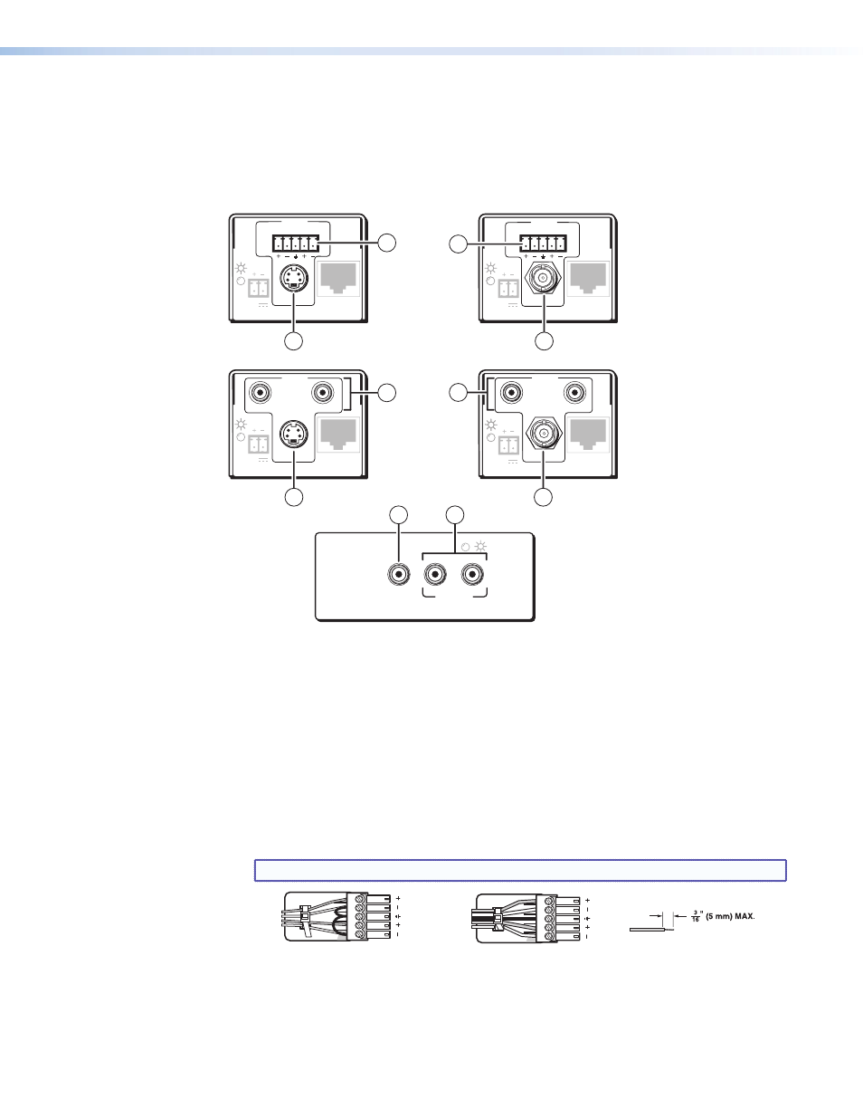
Transmitter Input Connections
Figure 8 shows all of the combinations of video and audio input connectors that you may
encounter with your MTP transmitter.
12V
0.5a
INPUT
MTP T AV RCA
OUTPUT
MAX
VIDEO
L
R
INPUT
L
R
12V
0.5a
MTP T AV
OUTPUT
MAX
VIDEO
12V
0.5a
INPUT
L
R
MTP T SV A
OUTPUT
MAX
S-VIDEO
12V
0.5a
INPUT
MTP T SV A RCA
OUTPUT
MAX
S-VIDEO
L
R
MTP T SV A RCA,
Rear Panel
MTP T AV RCA,
Rear Panel
MTP T AV AAP,
Front Panel
MTP T SV A,
Rear Panel
MTP T AV,
Rear Panel
AUDIO IN
VIDEO
IN
L
R
MTP T AV
2
1
2
1
4
4
L
2
3
3
4
Figure 8.
Video and Audio Input Connections
a
S-video connector (SV models) — Connect an S-video input to this 4-pin mini DIN
connector.
b
Composite video connector (AV models) — Connect a composite video input to this
connector (female RCA on the MTP T AV AAP, female BNC on all other models).
c
Audio input captive screw connector (MTP T SV A, MTP T AV) — Connect a
balanced or unbalanced audio input to this 3.5 mm, 5-pole captive screw connector.
Connectors are included with each MTP, but you must supply the audio cable. See
figure 9 to wire a connector for the appropriate input type. Use the supplied tie-wrap to
secure the audio cable to the extended tail of the connector.
NOTE: High impedance is generally over 800 ohms.
Unbalanced Stereo Input
Do not tin the wires!
Tip
Sleeve
Sleeve
Tip
LR
Balanced Stereo Input
Tip
Ring
Tip
Ring
LR
Sleeves
Figure 9.
Captive Screw Input Connector Wiring