Installation, cont’d, Setting the -6db jumpers – Extron Electronics MLS 506SA User Manual
Page 18
Installation, cont’d
MediaLink Switchers • Installation
2-12
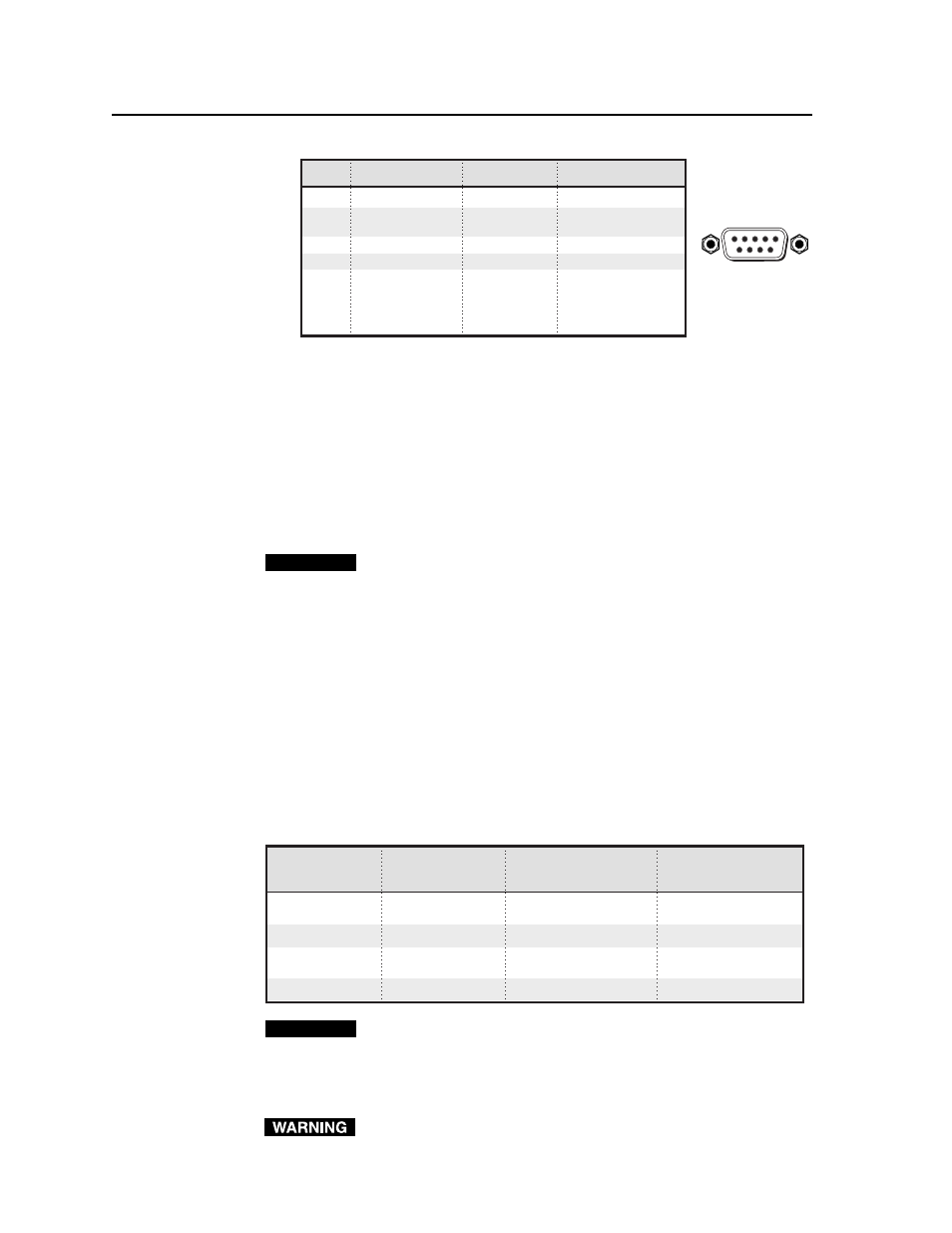
Pin
RS-232 function Description
Contact closure
1
–
Input 1
Input 1
2
Tx
Transmit data
–
3
Rx
Receive data
–
4
–
Input 2
Input 2
5
Gnd
Signal ground
–
6
–
Input 3
Input 3
7
–
Input 4
Input 4
8
–
Input 5
Input 5
9
–
Input 6
Input 6
DB9 Pin Locations
Female
5
1
9
6
•
For a stand-alone MLS switcher, connect a cable from the host computer
or a third party control system to this 9-pin D connector to set up and
remotely control the switcher. Alternatively, connect a contact closure
keypad to this connector for remote control of input selection.
•
For an MLS switcher slaved to an MLC controller, connect a cable from
the MLC’s MLS/Power port to the switcher’s MLC/IR connector (not to
the 9-pin RS-232 port). Once the system has been cabled and set up via
the Windows-based software, the MLC or a host computer communicat-
ing through the MLC can be used to remotely control the switcher. Refer
to chapter four of the MLC 206 User’s Manual and the MediaLink Control
Program help file for details on configuring an MLC-MLS system.
CAUTION
If the switcher is connected to an MLC 206 controller via the MLC/IR
port, do not connect an RS-232 device to the MLS’s 9-pin RS-232/Contact
Closure port. Conflicts between RS-232 signals received from both ports
could cause system disruptions.
When an MLC 206 is connected to the MLC/IR port, a contact closure
device may be attached to the 9-pin connector.
Setting the -6dB Jumpers
In the MLS switchers, when audio signals are converted from an unbalanced input
to a balanced output, an additional +6dB gain is applied to the output signal. To
remove the +6dB gain from the balanced output or to apply a 6dB attenuation to
unbalanced output, jumper headers have been applied to pins inside the switcher.
The jumper headers can be removed if you would like to restore the +6dB gain.
The -6dB attenuation can be set separately for the left and right audio channels by
removing one of the jumper headers.
Input signal
Output signal
Gain/attenuation
Gain/attenuation
with jumpers
without jumpers
Unbalanced
Unbalanced
-6dB
0dB
Unbalanced
Balanced
0dB
+6dB
Balanced
Unbalanced
-6dB
0dB
Balanced
Balanced
0dB
+6dB
CAUTION
Changes to settings inside the unit must be performed by authorized
service personnel only.
Follow these steps to set the -6dB jumpers in any MediaLink Switcher.
1.
Disconnect the AC power cord from the MLS to remove power from the unit.
To prevent electric shock, always unplug the MLS switcher from the AC
power source before opening the enclosure.