Control connections – Extron Electronics MLS 506SA User Manual
Page 17
2-11
MediaLink Switchers • Installation
Control connections
12
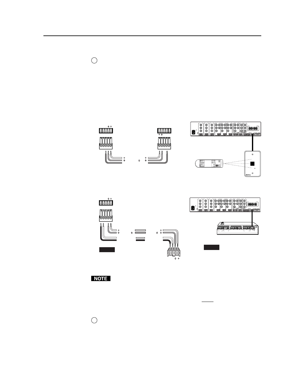
MLC/IR port
— This port allows you to provide remote control of the
switcher. Connect a cable between this port and an optional Extron MLC 206
MediaLink Controller or an optional IR Link IR signal repeater.
• The MLC provides remote control of input switching and volume.
• The IR Link accepts modulated IR signals from a remote control so the
remote control can be used for selecting the switcher’s inputs.
Extron Comm-Link cable is recommended for this connection. If you use
Comm-Link cable, the switcher and controller can be up to 250 feet (76.2 m)
apart. Wire the captive screw connector for connection to either an IR Link or
an MLC 206 as shown below.
MLS 506MA Rear Panel
100-240V 0.2A 50/60 Hz
.5A MAX
INPUT 1
VIDEO
Y
C
R-Y
B-Y
YUV
Y
R-Y
B-Y
VIDEO
S-VIDEO
Y
C
INPUT 2
VIDEO
Y
C
R-Y
B-Y
INPUT 3
VIDEO
Y
C
R-Y
B-Y
INPUT 4
R
H/
HV
G
V
B
INPUT 5
R
H/
HV
G
V
B
INPUT 6
R
H/
HV
G
V
B
RGB
R
H/
HV
G
V
B
4 ohm
MONO AMPLIFIED OUTPUT
COMM
8 ohm
70V
L
R
L
R
L
R
L
R
AUX/MIX
EFFECTS
L
R
SEND
L
R
RETURN
MLC/IR
RS232
CONTACT CLOSURE
A B C
AUDIO OUT
FIXED
VARIABLE
L
R
L
R
L
L
R
R
L
R
MLC/IR
A B C
MLS 506MA Rear Panel
MediaLink Switcher to an IR Link
MediaLink Switcher to an MLC 206
100-240V 0.2A 50/60 Hz
.5A MAX
INPUT 1
VIDEO
Y
C
R-Y
B-Y
YUV
Y
R-Y
B-Y
VIDEO
S-VIDEO
Y
C
INPUT 2
VIDEO
Y
C
R-Y
B-Y
INPUT 3
VIDEO
Y
C
R-Y
B-Y
INPUT 4
R
H/
HV
G
V
B
INPUT 5
R
H/
HV
G
V
B
INPUT 6
R
H/
HV
G
V
B
RGB
R
H/
HV
G
V
B
4 ohm
MONO AMPLIFIED OUTPUT
COMM
8 ohm
70V
L
R
L
R
L
R
L
R
AUX/MIX
EFFECTS
L
R
SEND
L
R
RETURN
MLC/IR
RS232
CONTACT CLOSURE
A B C
AUDIO OUT
FIXED
VARIABLE
L
R
L
R
L
L
R
R
L
R
Switcher
rear panel
MLC/IR port
IR Link
port
NOTE
If you use cable that has a
drain wire, tie the drain wire
to ground at both ends.
A B C D E
A B C
IR
Display/Source Control
Extron Switcher Control
Relays
IR / RCM
RS-232
D E
A B C
A B
D
1A 1B 2A 2B 3A 3B
1 2 3 4 5 6
Tally Out
MLS/Power
33-644-01 A
07 01
Pr
inted in the
USA
MLC 206 Bottom Panel
Ground ( )
+12VDC
IR (IR Link)
C
IR Link
MLA-Remote
SIGNAL
IR LINK
MLC/IR
A B C
MediaLink
Switcher
rear panel
MLC/IR port
NOTE
The switcher provides
power to the controller.
MLC
MLS/Power
port
Ground ( )
+12VDC
Transmit (Tx)
B
Receive (Rx)
A
A B
MLS / Power
Transmit (Tx)
Receive (Rx)
+12VDC
Ground ( )
B
A
IR
A B C D E
D
If the switcher is connected to an MLC 206 controller via the MLC/IR port, do
not connect an RS-232 device to the MLS’s 9-pin RS-232/Contact Closure
port. The 9-pin D and 5-pole captive screw connectors are both for RS-232
control.
Connect devices to both ports at the same time only if
• the 9-pin connector is used for contact closure and
• the MLC/IR port is used for RS-232.
13
RS-232/Contact Closure port
— This port can function as an RS-232 port or as
a contact closure port. Do not connect RS-232 devices to both this and the
MLC/IR port. See the above note.