Operation – Extron Electronics IN2118 User Manual
Page 17
15
©2001 - Inline, Inc. IN2118 Operation Manual - Preliminary 01/31/01
Operation
HORIZONTAL POSITION CONTROL
The location of the horizontal position control is shown in the Faceplate A Connectors and
Controls Diagram on the previous page. This control adjusts the position of the image on the
data display device. The horizontal position control has no effect on the local computer monitor.
If the horizontal position adjustment is set to an extreme position on either the display device or
the IN2118 Interface, the output image may appear dark and / or the colors may be displayed
improperly. To position the video image and achieve optimum picture quality:
1. Set the display device’s horizontal position control to the center of its adjustment range.
2. Adjust the horizontal position control on the IN2118 Interface until the picture is
centered properly on the display device.
Note: The horizontal position control does not work with RGsB input signals.
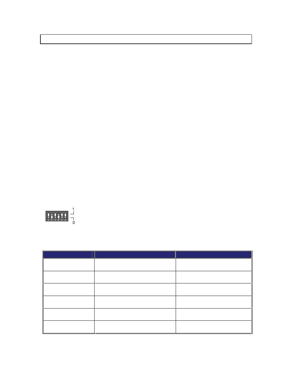
DIPSWITCH SETTINGS
Most installations will not require any changes to the dipswitch settings. The factory default and
specialized dipswitch settings are indicated below.
Note: The switches are located under the Dipswitch access plate (see the diagram on the previous
page).
Factory Default Settings:
Dipswitches ON: 2 & 4
Signal Format: Red / Green / Blue / Horizontal and Vertical Sync
Horizontal Position Control: Enabled
H & V Sync Polarity: Negative, Negative
Monitor Emulation: Disabled
The following table lists the functions of the 6 dipswitches:
DIPSWITCH
FUNCTION
SETTING
1
Horizontal Position
1 = Disabled
0 = Enabled
2
RGsB Output (sync on green)
1 = RGBS or RGBHV
0 = RGsB
3
RGBS or RGBHV Output (dip
switch 2 must be set to 1)
1 = RGBS
0 = RGBHV
4
RGBHV Output Sync Polarity
1 = Negative, Negative
0 = Mirror Input Polarities
5
Serration Pulse Removal (for
RGBS or RGsB output)
1 = Remove Serration Pulses
0 = Pass Serration Pulses
6
Monitor Emulation (VGA color /
MAC* 640 x 480)
1 = Emulation Disabled
0 = Emulation Enabled
*If monitor emulation is desired when using a MAC G3 (with 15-pin HD connector) or G4, dipswitch #6 must be set to 1.