Extron Electronics IN2118 User Manual
Page 12
10
IN2118 Operation Manual - Preliminary 01/31/01 ©2001 - Inline, Inc.
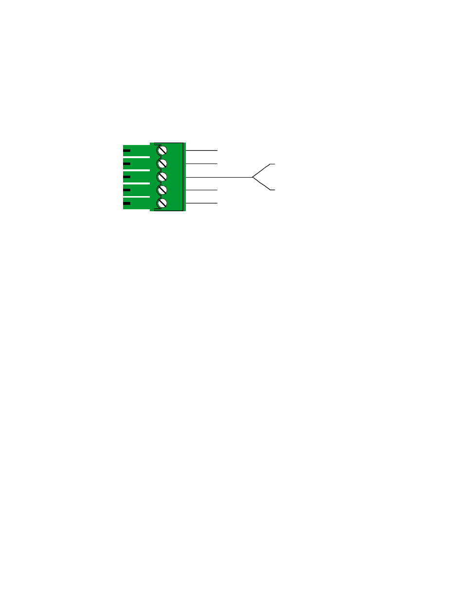
5. Connect the Left, Right and Ground Conductors on the audio cables to the 5-pin
captive screw terminal. This connector will accept stranded or solid cables from 20 - 26
AWG. The IN2118 Interface takes an unbalanced stereo audio input, buffers the signal
and outputs it as balanced stereo audio. This is desirable for systems where the audio
signal will be connected to equipment with balanced audio inputs, and is helpful in
preserving signal integrity and minimizing outside signal interference (which often occurs
while sending the audio signal over lengthy cable runs).
5LJKW *URXQG
/HIW *URXQG
/HIW
5LJKW
5LJKW
/HIW
6. Access the Dipswitches by removing the screws on the front plate (the IN9334 3/32”
Allen Wrench is included). Use the IN9339 Adjustment Tool to set the switches as
appropriate for your installation (a complete description of the dipswitch settings is
provided on page 15). The factory default output format is RGBS / RGBHV. If your
display device, routing system or cabling requires a different format, use the dipswitches
to change the output signal to RGsB. Replace the front plate and tighten the hex screws.
7. Connect the Remote Device to the 4-pin captive screw terminal (see the Remote Control
Operation Section on page 16).
8. Apply Power to the IN2118 using the IN9230 IEC (USA only) power cable (included).
9. Complete the Installation by turning the interface ON (the power switch is located to the
right of the A/C connector). The front panel LED (on the Interface) will illuminate.
FOR IN2118-A, D & G INSTALLATIONS:
10. Connect the Computer Graphics Card to the IN2118 15-pin video input port (a
Connectors and Controls Diagram is provided on page 14).
•
PC / MAC / SGI Computers with 15-pin HD Video Ports - can be connected via
IN8000M-1 / IN8200M-1 Series high-resolution coaxial VGA cables.
•
Older Macintosh (15-pin D) / SUN (13W3) / Workstations (4 or 5 BNC) - can be
connected using the appropriate input / output cables listed in the chart on the following
page.
11. Connect the Computer Sound Card Output (if applicable) to the IN2118 3.5mm female
stereo audio input connector using an IN8200-1 Series cable (15-pin HD with 3.5mm stereo
mini male), or an IN9106 audio patch cable (3.5mm stereo mini male to 3.5mm stereo mini
male). For computers with RCA connectors, use the IN9107 audio adapter cable [(1) 3.5mm
stereo mini male to (2) RCA male].