Installing the flexible conduit cable on a ps 124, Caution – Extron Electronics Flexible Conduit Adapter Kit User Manual
Page 2
Flexible Conduit Adapter Kit Installation Guide (Continued)
2
Installing the Flexible Conduit Cable on a PS 124
Install the flexible conduit cable assembly to the PS 124 as follows:
1.
Unplug the IEC power cord from the PS 124.
2.
Remove and retain the two Phillips head screws that secure the IEC plate to the PS 124 rear panel.
OUTPUTS
RED-
OVERLOAD
12 VDC TOTAL OUTPUT 4A
100-240 50-60Hz 2A MAX
Remove two screws.
IEC Plate
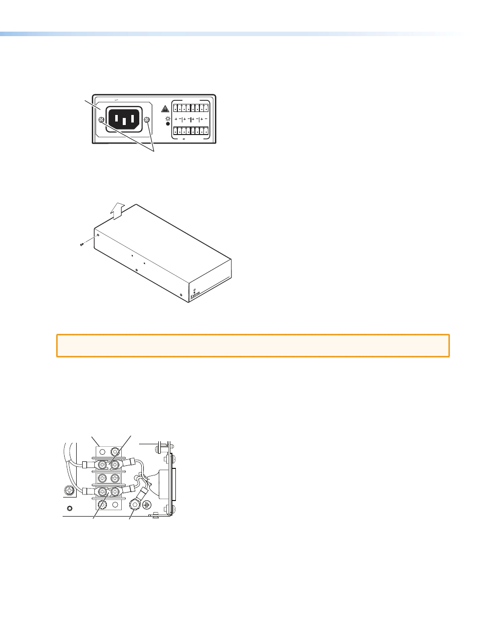
Figure 1.
Removing the IEC Plate
3.
Remove and retain the six screws that connect the top cover of the PS 124 to its bottom board.
RED-
OV
ERL
OA
D
P/S 12
4
12 VDC 4A PO
WER SUPP
LY
Remove three
screws on
each side.
Lift the cover
straight up.
Figure 2.
Removing the PS 124 Top Cover
4.
Carefully lift the top cover up, taking care not to remove it completely.
CAUTION:
Rough handling of the top cover can disconnect or damage the wiring that connects the front
panel LED.
5.
Use a standard screwdriver to loosen the screws holding the hot and
neutral
wires on the side of the terminal block
nearest the IEC plate (see figure 3, below).
6.
Unscrew the IEC connector ground wire from the ground wire nut on the bare metal bottom of the PS 124 enclosure.
7.
From the rear panel end, pull the IEC connector out of the enclosure.
8.
Thread the 12- or 14-gauge power wires through the length of the electrical conduit tube.
Hot Terminal
Neutral Terminal
Ground Wire Nut
Terminal Block
Figure 3.
Terminal Block and IEC Wiring
9.
Install the EMT adapter plate (with the conduit attached) into the opening from which you removed the IEC connector
in step 7 (see figure 4, on the next page). Use the Phillips head screws that you removed in step 2 to attach the EMT
adapter plate.