Step 4, Step 5, Step 6 – Extron Electronics Extender Plus Series Setup Guide User Manual
Page 2: Step 7, Step 8, Step 9, Connect power and turn the equipment on, Disconnect power from all the devices, Faceplate, Restore power to the devices
68‑2320‑50
Rev.
A
09 12
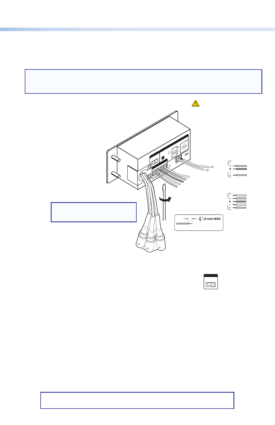
Step 4
Attach and wire the cables as shown in the image below. The Extender Plus D has the same
circuit board configuration. See
“Rear Panel Features and Cabling” in the Extender Plus
Series User Guide for more details.
NOTE:
If the Extender Plus AAP is installed in an Extron HSA 400 Series or 800 Series
surface access product, install the Extender into the faceplate before attaching the
cables.
Step 5
Connect power and turn the equipment on.
Step 6
Test the system and set the gain switch. Ensure that all devices
receive power. Check and adjust cabling and gain as needed.
Step 7
Disconnect power from all the devices.
Step 8
Mount the line driver into the electrical box or the Plus AAP model into the body of the HSA.
For the Extender Plus D, install the Decora
®
faceplate.
Step 9
Restore power to the devices.
COMPUTER
OU
T
EXTENDER Plus
D
L
R
NORM
MED
HIGH
STOR
E
60
Hz
1
2
ON
50
SELECT
POWER
12V
0.2 A MA
X
AUDIO OU
T
GAIN
EDI
D
0
1
2
3
45
6
7
8
9
A
B
C D
E
F
Audio
Unbalanced Output
Left Tip
NO Ground Here
Sleeve (s)
Right Tip
NO Ground Here
Balanced Output
Sleeve (s)
Left Tip
Right Tip
Left Ring
Right Ring
Sleeve (s)
Left Tip
Right Tip
Left Ring
Right Ring
L
A
udi
o
R
L
A
udi
o
R
12 VDC
Power
CAUTION
Do not tin the wires!
For unbalanced audio, connect the sleeve(s)
to the ground contact.
DO NOT
connect the
sleeve(s) to the negative (-) contacts.
Extron USA Headquarters
© 2012 Extron Electronics All rights reserved.
NORM
ME
D
HIGH
GAIN
Gain Switch
(viewed
from front)
NOTE:
Horizontal sync = black
Vertical sync = yellow