System startup and operation, Indications – Extron Electronics FOX USB Extender User Guide User Manual
Page 12
d
DIP Switch —
Emulation (down) position — Enables the peripheral emulation, which is internal
to the transmitter. This emulation allows connected hosts, some of which require a
connected USB device, to boot up normally.
Bypass (up) position — Bypasses the internal peripheral emulation of the
transmitter.
NOTES:
•
The FOX USB Extender system supports up to four USB hubs connected
to the receiver when the DIP switch on the transmitter is in the Bypass
position. The system supports up to three hubs when the DIP switch is in
the Emulation position.
•
DIP switch 2 has no function.
e
Hub connectors — These female USB Type A connectors support up to four USB
devices. Do not connect devices at this time; see “
The connections are USB 2.0 compatible, and can provide +5 VDC at up to 500 mA to
connected USB peripherals requiring power.
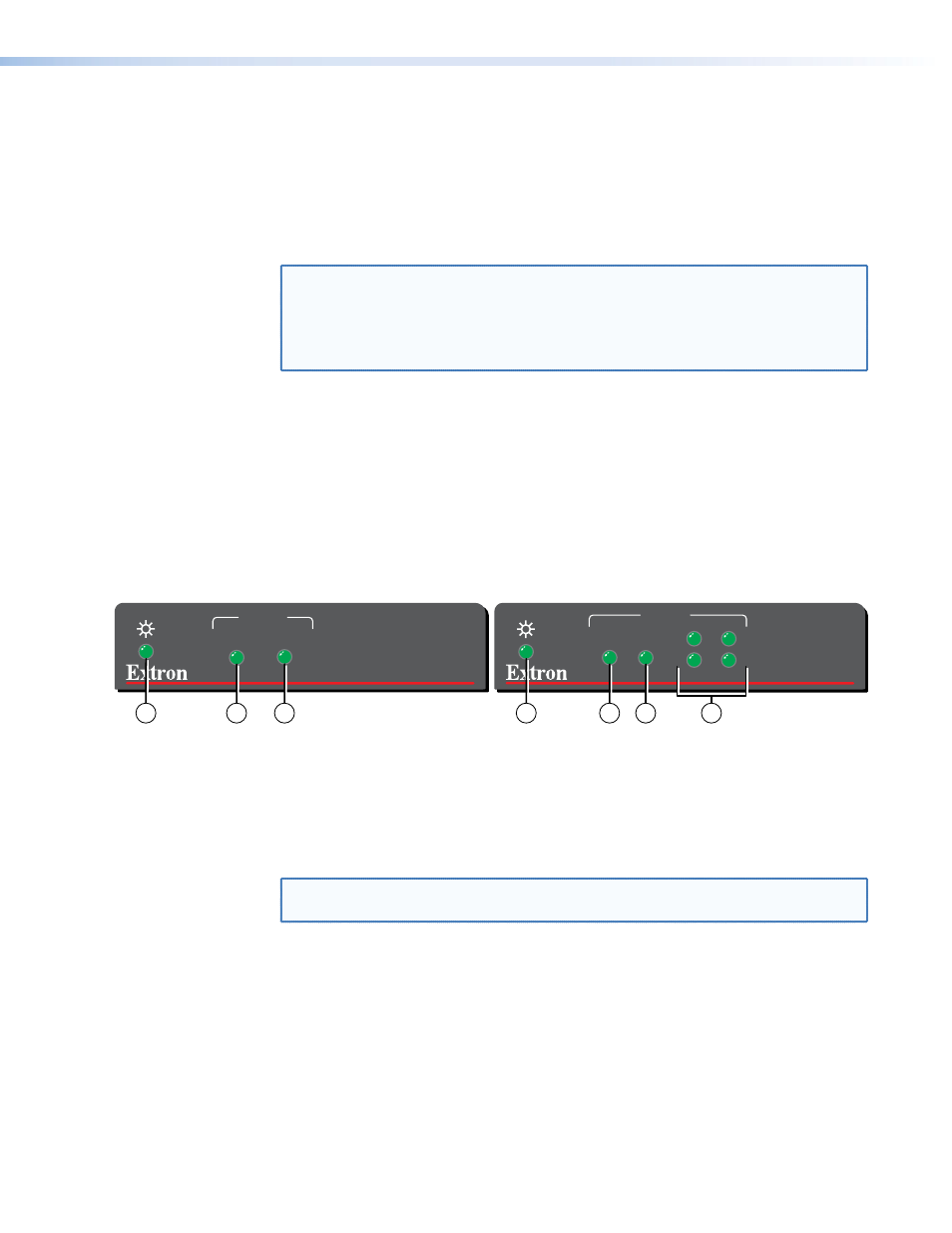
System Startup and Operation
Indications
LINK
HOST
ACTIVITY
FOX USB EXTENDER Tx
LINK
ACTIVITY
1
HOST
HUB
2
3
4
FOX USB EXTENDER Rx
Receiver
Transmitter
4
3
4
3
2
1
5
Figure 4.
Front Panel Indications
a
Power LED (transmitter) — Indicates that the transmitter is receiving power from
an external power supply.
b
Power LED (receiver) — Indicates that the receiver is receiving power from an
external power supply.
c
Link LED — Indicates that the unit is receiving light on its rear panel Rx connector.
NOTE: The receiver Link LED indicates light from the transmitter.
The transmitter Link LED indicates light from the receiver.
d
Host LED — Indicates that the Extender is communicating with the computer
connected to the rear panel Host port on the transmitter.
e
Hub LEDs — Indicate that the receiver is communicating with the USB peripheral
connected to the rear panel Hub port on the receiver.
FOX USB Extender • Installation and Operation
6