Wiring the audio connectors, Front panel features, Ab c – Extron Electronics FOX AEX 108 User Guide User Manual
Page 13
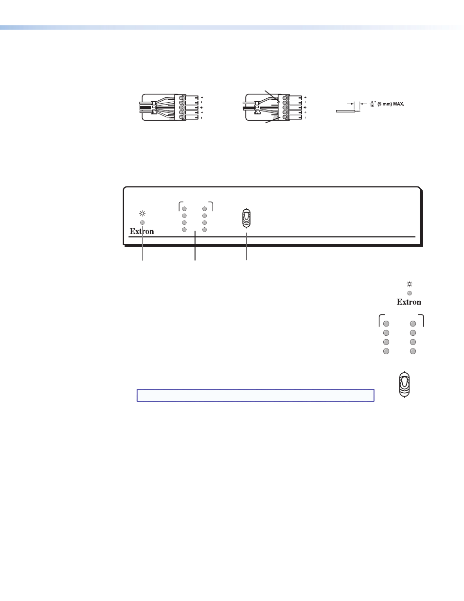
Wiring the Audio Connectors
Connect a 3.5 mm, 5-pole captive screw audio connectors for stereo audio output. This
output is unamplified line level audio. Wire the connector as show in figure 2.
Do not tin the wires!
Balanced Audio Output
Tip
Ring
Tip
Ring
Sleeves
Unbalanced Audio Output
Tip
No Ground Here
No Ground Here
Tip
Sleeves
LR
LR
Figure 5.
Captive Screw Connector Wiring for Audio Signals
Front Panel Features
1
2
3
4
5
6
7
8
AUDIO SIGNAL
INPUT DATA RATE
FIBER AUDIO EXTRACTOR
FOX AEX 108
2.125G
4.25G
a
b
c
Figure 6.
Front Panel Features
a
Power LED indicator — Lights when power is applied.
b
Audio Signal LED indicators — Each indicator lights when an audio
signal above –35 dBV is detected on the associated fiber input. The LED
lights immediately when the signal goes above that threshold, but turns
off after the audio signal level remains below the threshold for
10 seconds.
c
Recessed toggle switch — A recessed toggle switch that selects the
input reclocking to maintain signal integrity on all inputs. Selects between
2G and 4G input data rates.
NOTE: The default switch position is down (4G).
1
2
3
4
5
6
7
8
AUDIO SIGNAL
INPUT DATA RATE
2.125G
4.25G
FOX AEX 108 • Installation and Operation
7