Installation and operation, Rear panel features, Figure 4. fox aex 108 rear panel – Extron Electronics FOX AEX 108 User Guide User Manual
Page 12
Installation and
Operation
This section provides cabling and operating information for the FOX AEX 108. Topics in this
section include:
•
•
•
Rear Panel Features
100-240V ~ 0.3A Max.
50/60 Hz
AUDIO R
L
Rx
1
Tx
+ -
-
+
AUDIO R
L
Rx
2
Tx
+ -
-
+
AUDIO R
L
Rx
3
Tx
+ -
-
+
AUDIO R
L
Rx
4
Tx
+ -
-
+
AUDIO R
L
Rx
5
Tx
+ -
-
+
AUDIO R
L
Rx
6
Tx
+ -
-
+
AUDIO R
L
Rx
7
Tx
+ -
-
+
AUDIO R
L
Rx
8
Tx
+ -
-
+
a
З Й
c
d
Й
З
Й
З
Й
З
Й
З
Й
З
Й
З
Й
З
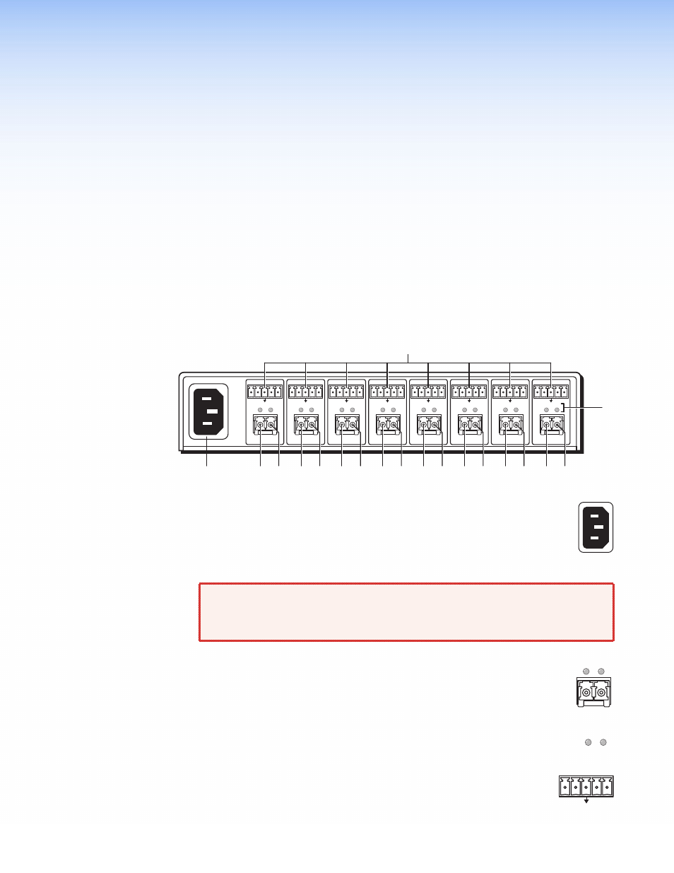
Figure 4.
FOX AEX 108 Rear Panel
a
AC power connector — Plug a standard IEC power cord into the connector to
connect the FOX AEX 108 to a 120 V or 240 VAC, 50 or 60 Hz power source.
b
Fiber optic connectors — One dual port LC SFP module for fiber Tx or Rx
transmission with two LEDs for fiber link status.
WARNING: These units output continuous invisible light, which may be harmful
to the eyes; use with caution. For additional safety, plug the attached
dust caps into the optical transceivers when the fiber cable is
unplugged.
Ç
Tx connector — Connect a fiber optic cable to the Tx LC connector and
Rx port of a FOX receiver.
É
Rx connector — Connect a fiber optic cable to the fiber output (OUT) of
the matrix to the Rx of an extraction point.
c
Tx and Rx indicator LEDs — The optical Tx and Rx LED lights indicate fiber
light presence. The Rx LED lights when the Rx device receives light from fiber 1.
The Tx LED lights as soon as there is light presence on the Rx LED.
d
Audio connectors — Insert a 3.5 mm, 5-pole captive screw audio
connector for each extraction point.
AUDIO R
L
Rx
1
Tx
+ -
-
+
AUDIO R
L
Rx
1
Tx
+ -
-
+
AUDIO R
L
+ -
-
+
100-240V ~ 0.3A Max.
50/60 Hz
6
FOX AEX 108 • Installation and Operation