Installation, cont’d, Front panel features – Extron Electronics DVS 150 User Manual
Page 16
Installation, cont’d
DVS 100 and DVS 150 Installation
2-6
If you cable the scaler for sync on green (RGsB or SOG) output,
you must also configure the scaler for SOG via the configuration
menu. See “Configuring the Scaler” on page 2-7 for instructions.
You can install and run two output devices simultaneously, one
using BNC connectors, and the other using the RGB connector.
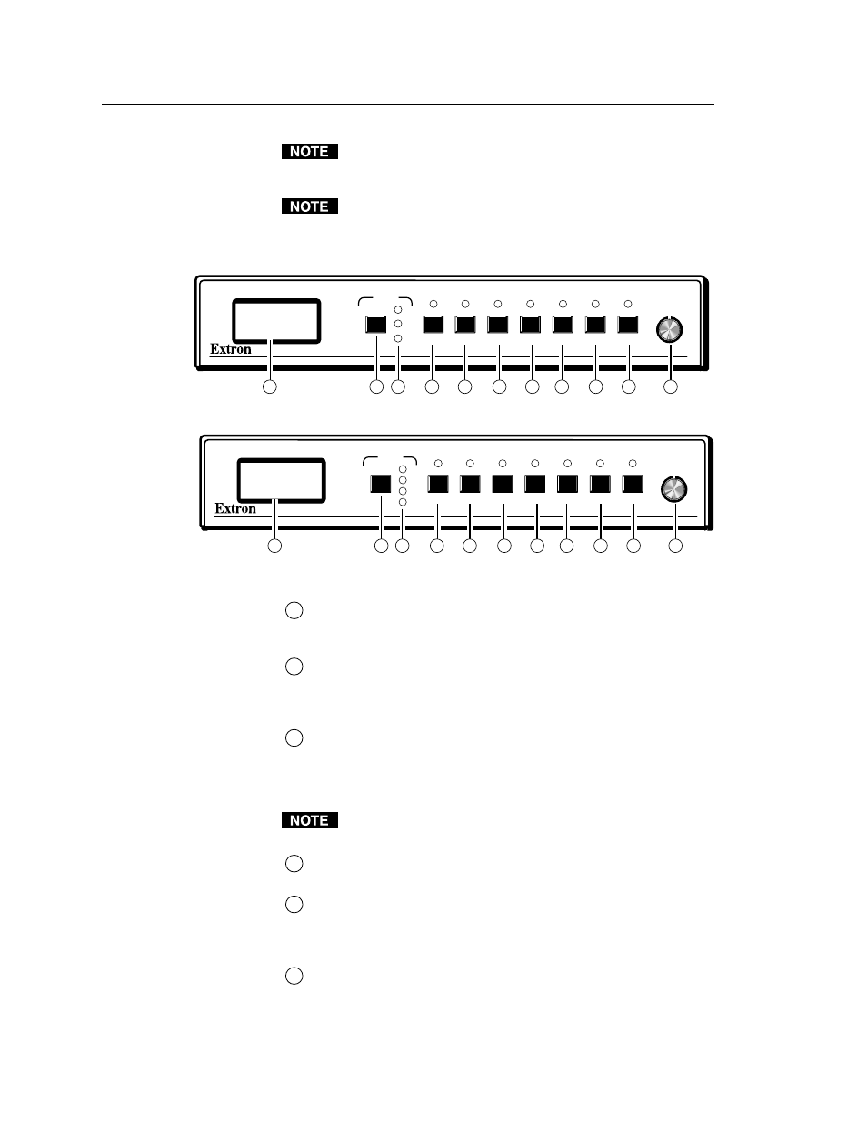
Front Panel Features
Figure 8 — DVS 100 front panel
Figure 9 — DVS 150 front panel
1
LCD —
Displays configuration menus and status information.
See “Configuring the Scaler” on page 2-7 and “Adjusting an
image” on page 3-2.
2
Input selection button —
Allows you to select the input type (see
“Choosing the input source” on page 3-2). If the image has been
frozen via an RS-232 command, the input button cancels the freeze
function (see “Freeze mode” on page 3-4).
3
Input LEDs
— Display the active input. If LED (light emitting
diode) 1 is lit, the input is composite video. If LED 2 is lit, the
input is component video. If LED 3 is lit, the input is S-video. If
LED 4 is lit , the input is RGB (from the pass-though connector;
DVS 150 only).
The following adjustments are not available if the input is RGB
pass-through (DVS 150 only).
4
Color control button —
Allows you to adjust the image color. For
more information, see “Adjusting an image” on page 3-2.
5
Tint control button —
Allows you to adjust the image tint. For
more information, see “Adjusting an image” on page 3-2. This
control is not available if the input is component video, PAL, or
SECAM.
6
Brightness control button —
Allows you to adjust the image
brightness. For more information, see “Adjusting an image” on
page 3-2.
RATE
V SHIFT
H SHIFT
CONT
BRIGHT
TINT
COLOR
1
2
3
DVS 100
DIGITAL VIDEO SCALER
INPUT
1
2
3
4
5
7
8
9
10
11
6
RATE
V SHIFT
H SHIFT
CONT
BRIGHT
TINT
COLOR
1
2
3
4
DVS 150
DIGITAL VIDEO SCALER
INPUT
1
2
3
4
5
6
7
8
9
10
11