Making connections, Connect the hardware – Extron Electronics DMS 1600_2000_3200_3600 Setup Guide User Manual
Page 7
6
DMS 1600, DMS 2000, DMS 3200, DMS 3600 • Installation
7
DMS 1600, DMS 2000, DMS 3200, DMS 3600 • Installation
ANAHEIM, CA
RESET
RS232/RS422
REMOTE
LAN
ACT LINK
REDUNDANT
PRIMARY
PRIMARY POWER SUPPLY
REDUNDANT POWER SUPPLY
FAN ASSIMBLY
FAN ASSIMBLY
100-240V
50-60Hz
2.5A MAX.
100-240V
50-60Hz
2.5A MAX.
DISCONNECT BOTH POWER
CORDS BEFORE SERVICING
N
1 - 4
5 - 8
9 - 12
13- 16
17 - 20
21 - 24
25 - 28
29- 32
33 - 36
A
B
TMDS
FIBER
INPUTS
C
D
A
B
TMDS
FIBER
OUTPUTS
DMS FIBER 44
C
D
A
B
TMDS
FIBER
INPUTS
C
D
A
B
TMDS
FIBER
OUTPUTS
DMS FIBER 44
C
D
A
B
TMDS
FIBER
INPUTS
C
D
A
B
TMDS
FIBER
INPUTS
C
D
A
B
TMDS
FIBER
INPUTS
C
D
A
B
DVI-D INPUTS
DVI-D OUTPUTS
C
D
A
B
C
D
DMS 44 DVI
A
B
DVI-D INPUTS
DVI-D OUTPUTS
C
D
A
B
C
D
DMS 44 DVI
A
B
DVI-D INPUTS
DVI-D OUTPUTS
C
D
A
B
C
D
DMS 44 DVI
A
B
DVI-D INPUTS
DVI-D OUTPUTS
C
D
A
B
C
D
DMS 44 DVI
9
5
6
7
9
8
1
1
10
2
3
4
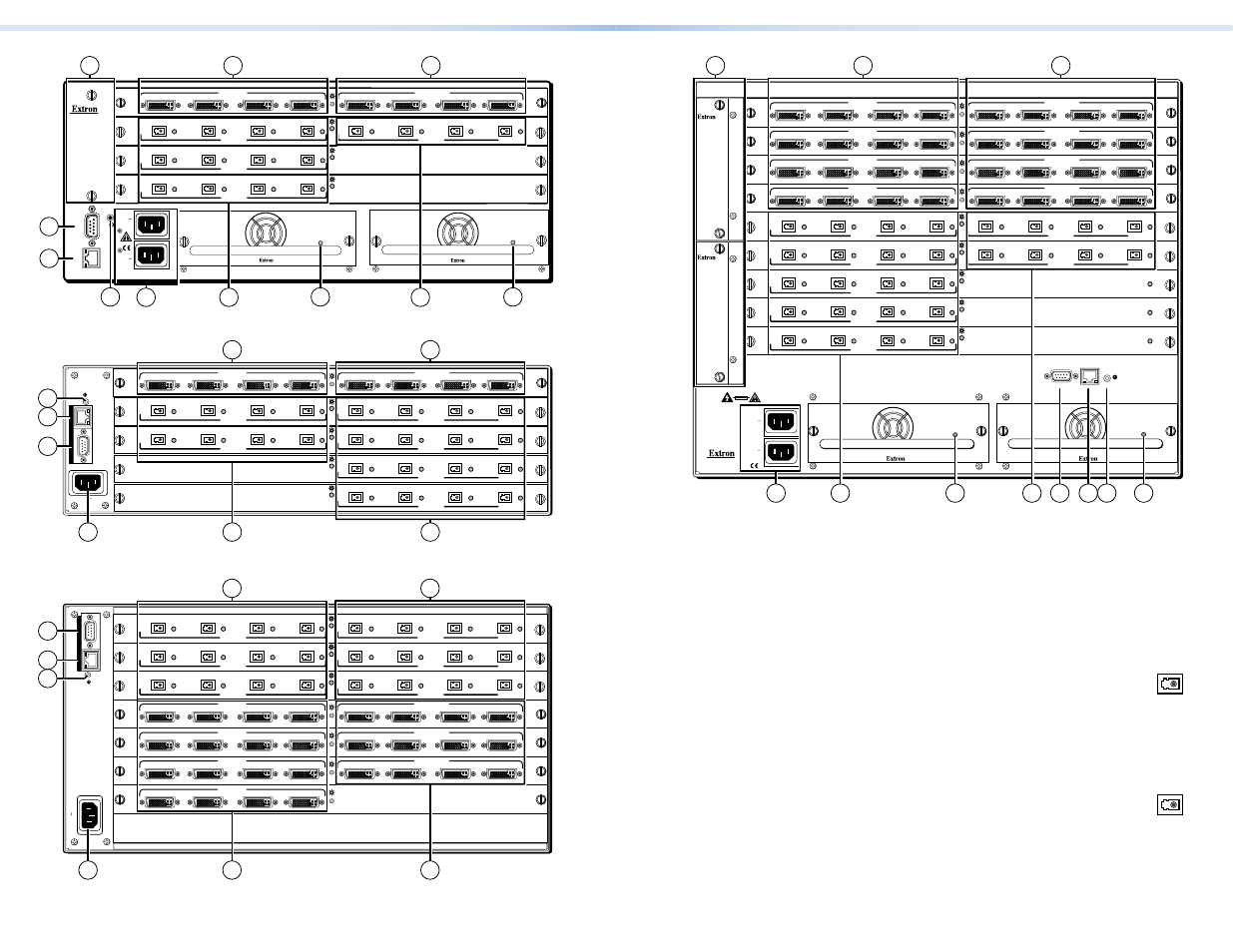
Figure 6.
DMS 3600 Features
Making Connections
a
DVI-I Input connectors — Connect DVI cables between these
ports and the DVI output ports of the digital video sources.
b
DVI-I Output connectors — Connect DVI displays for the routed DVI
image.
c
Fiber optic input ports — Connect fiber optic cables to the
Input LC connectors.
Connect the opposite ends of these fiber optic cables to the Output
connectors on DFX 100 Tx transmitters.
Input LEDs — These LEDs light amber to indicate fiber connections.
These LEDs light green to indicate signal detection.
d
Fiber optic output ports — Connect fiber optic cables to the
Input LC connectors.
Connect the opposite ends of these fiber optic cables to the Input
connectors on DFX 100 Rx receivers.
Input LEDs — These LED light amber to indicate fiber connections.
These LEDs light green to indicate signal transmissions.
ANAHEIM, CA
RESET
REMO
TE
RS-232/RS-422
LAN
AC
T LINK
REDUNDANT
100-240V
50-60Hz
1.2A MAX.
PRIMARY
100-240V
50-60Hz
1.2A MAX.
DISCONNECT BO
TH PO
WER
CORDS BEFORE SER
VICING
PRIMARY POWER SUPPLY
REDUNDANT POWER SUPPLY
1 - 4
5 - 8
9 - 12
13 - 16
A
B
TMDS
FIBER
INPUTS
C
D
A
B
TMDS
FIBER
OUTPUTS
DMS FIBER 44
C
D
A
B
DVI-D INPUTS
DVI-D OUTPUTS
C
D
A
B
C
D
DMS 44 DVI
A
B
TMDS
FIBER
INPUTS
C
D
DMS FIBER 44
A
B
TMDS
FIBER
INPUTS
C
D
DMS FIBER 44
5
6
9
7
9
REDUNDANT
100-240V
50-60Hz
1.2A MAX.
PRIMARY
100-240V
50-60Hz
1.2A MAX.
DISCONNECT BO
TH PO
WER
CORDS BEFORE SER
VICING
1
1
2
10
8
3
4
A
B
C
D
A
B
C
D
RESET
LAN
REMOTE
100-240V 50/60Hz
2.0A MAX
1 - 4
5 - 8
9 - 12
13- 16
17 - 20
A
B
TMDS
FIBER
INPUTS
C
D
A
B
TMDS
FIBER
OUTPUTS
DMS FIBER 44
C
D
A
B
TMDS
FIBER
OUTPUTS
DMS FIBER 44
C
D
A
B
TMDS
FIBER
OUTPUTS
DMS FIBER 44
C
D
A
B
TMDS
FIBER
INPUTS
C
D
A
B
TMDS
FIBER
OUTPUTS
DMS FIBER 44
C
D
A
B
DVI-D INPUTS
DVI-D OUTPUTS
C
D
A
B
C
D
DMS 44 DVI
7
6
1
1
2
3
4
5
8
RESET
1 - 4
5 - 8
9 - 12
13- 16
17 - 20
21 - 24
25 - 28
29- 32
LAN
REMOTE
100-240V 50/60Hz
3.0A MAX
A
B
TMDS
FIBER
INPUTS
C
D
A
B
TMDS
FIBER
OUTPUTS
DMS FIBER 44
C
D
A
B
TMDS
FIBER
INPUTS
C
D
A
B
TMDS
FIBER
OUTPUTS
DMS FIBER 44
C
D
A
B
TMDS
FIBER
INPUTS
C
D
A
B
TMDS
FIBER
OUTPUTS
DMS FIBER 44
C
D
A
B
DVI-D INPUTS
C
D
DMS 44 DVI
A
B
DVI-D INPUTS
DVI-D OUTPUTS
C
D
A
B
C
D
DMS 44 DVI
A
B
DVI-D INPUTS
DVI-D OUTPUTS
C
D
A
B
C
D
DMS 44 DVI
A
B
DVI-D INPUTS
DVI-D OUTPUTS
C
D
A
B
C
D
DMS 44 DVI
7
6
1
3
4
1
2
5
8
Figure 4.
DMS 2000 Features
Figure 5.
DMS 3200 Features
Figure 3.
DMS 1600 Features