Receiver connections, Receiver rear panel – Extron Electronics DTP DVI 230 D User Guide User Manual
Page 14
DTP DVI 230 D Transmitter and Receiver • Installation and Operation
8
Connect the opposite end of the twisted pair cable to the receiver input port shown in
figure 7 (see
TP Cable Termination and Recommendations
on page 10 to properly
wire the RJ-45 connectors).
NOTES:
•
In order to fit in the junction box, the twisted pair cables and RJ-45 connectors
should not have a boot installed.
•
Do not use Extron STP201 or Skew-Free UTP series cable with these
products
Receiver Connections
The DTP DVI 230 D receiver is in an enclosure that can be mounted in UL-listed standard
wall boxes with Decora-style face plates.
Receiver Rear Panel
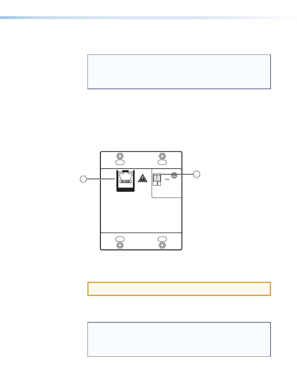
Figure 7 shows the rear panel of the DTP DVI 230 D receiver.
DO NOT
CONNECT
TO LAN
DTP 230 D Rx
POWER
12V
0.8 A MAX
SIG
LINK
DTP IN
+ -
1
2
Figure 7.
DTP DVI 230 D Receiver Rear Panel Connectors
a
Receiver input port — Connect one end of a twisted pair cable to this RJ-45 input
port.
ATTENTION: Do not connect this device to a telecommunications or computer
data network.
Connect the opposite end to the RJ-45 output (see figure 7 above) on the transmitter
(see
TP Cable Termination and Recommendations
on page 10 to properly wire the
RJ-45 connectors).
NOTES:
•
In order to fit in the junction box, the twisted pair cables and RJ-45 connectors
should not have a boot installed.
•
Do not use Extron STP201 or Skew-Free UTP series cable with these
products