Rs-232 and ir connector wiring, Operation, Rs-232 communication (see – Extron Electronics DTP HDMI 230 D User Guide User Manual
Page 18
DTP HDMI 230 D Transmitter and Receiver • Installation and Operation
12
RS-232 and IR Connector Wiring
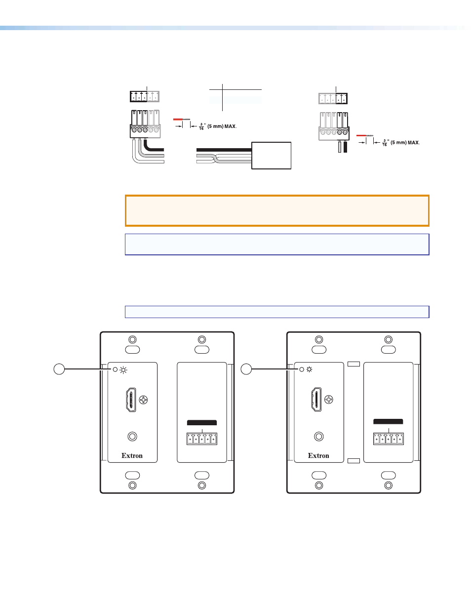
Figure
11
shows how to wire the RS-232 and IR connector for the DTP HDMI 230 D units.
Do not tin the wires!
Controlling
Device
Ground (G)
Receive (Rx)
Transmit (Tx)
Ground (G)
Receive (Rx)
Transmit (Tx)
Bidirectional
Function
Pin
TX
RX
Gnd
Transmit data
Receive data
Signal ground
IR
Tx Rx G
Tx Rx
RS-232
IR
Tx Rx G
Tx Rx
Do not tin the wires!
RS-232
Figure 11.
RS-232 and IR Connector Wiring
ATTENTION: The length of the exposed (stripped) copper wires is important.
The ideal length is 3/16 inch (5 mm). Longer bare wires can short together. Shorter
wires are not as secure in the connectors and could be pulled out.
NOTE: Do not tin the power supply leads before installing them in the direct insertion
connector. Tinned wires are not as secure in the connectors and could be pulled out.
Operation
Figure 12 shows the power indicator on the Decora transmitter.
NOTE: Both transmitter and receiver have power indicators in the location shown.
INPUTS
AUDIO
Tx Rx G Tx Rx
RS-232
IR
OVER DTP
OUTPUTS
AUDIO
Tx Rx G Tx Rx
RS-232
IR
OVER DTP
1
2
Figure 12.
DTP HDMI 230 D Transmitter and Receiver Power Indicators