Vga connector wiring – Extron Electronics DTP T USW 233 User Guide User Manual
Page 11
DTP T USW 233 • Installation and Operation
6
Supported cables
The DTP T USW 233 is compatible with CAT 5e, 6, 6a, and 7 shielded twisted pair (F/UTP,
SF/UTP, and S/FTP) and unshielded twisted pair (U/UTP) cable.
Cable recommendations
Extron recommends using the following practices to achieve full transmission distances up
to 230 feet (70 m) and reduce transmission errors.
•
Use the following Extron XTP DTP 24 SF/UTP cables and DTP 24 connectors for the
best performance:
•
XTP DTP 24/1000
Non-Plenum 1000’ (305 m) spool
22-236-03
•
XTP DTP 24P/1000 Plenum 1000’ (305 m) spool
22-235-03
•
XTP DTP 24 Plug
Package of 10
101-005-02
•
If not using XTP DTP 24 cable, at a minimum, Extron recommends 24 AWG, solid
conductor, STP cable with a minimum bandwidth of 400 MHz.
•
Terminate cables with shielded connectors to the TIA/EIA T 568 B standard.
•
Use no more than two pass-through points, which may include patch points, punch
down connectors, couplers, and power injectors. If these pass-through points are
required, use CAT 6 or 6a shielded couplers and punch down connectors.
NOTE: When using TP cable in bundles or conduits, consider the following:
•
Do not exceed 40% fill capacity in conduits.
•
Do not comb the cable for the first 20 meters, where cables are straightened,
aligned, and secured in tight bundles.
•
Loosely place cables and limit the use of tie wraps or Velcro
®
.
•
Separate twisted pair cables from AC power cables.
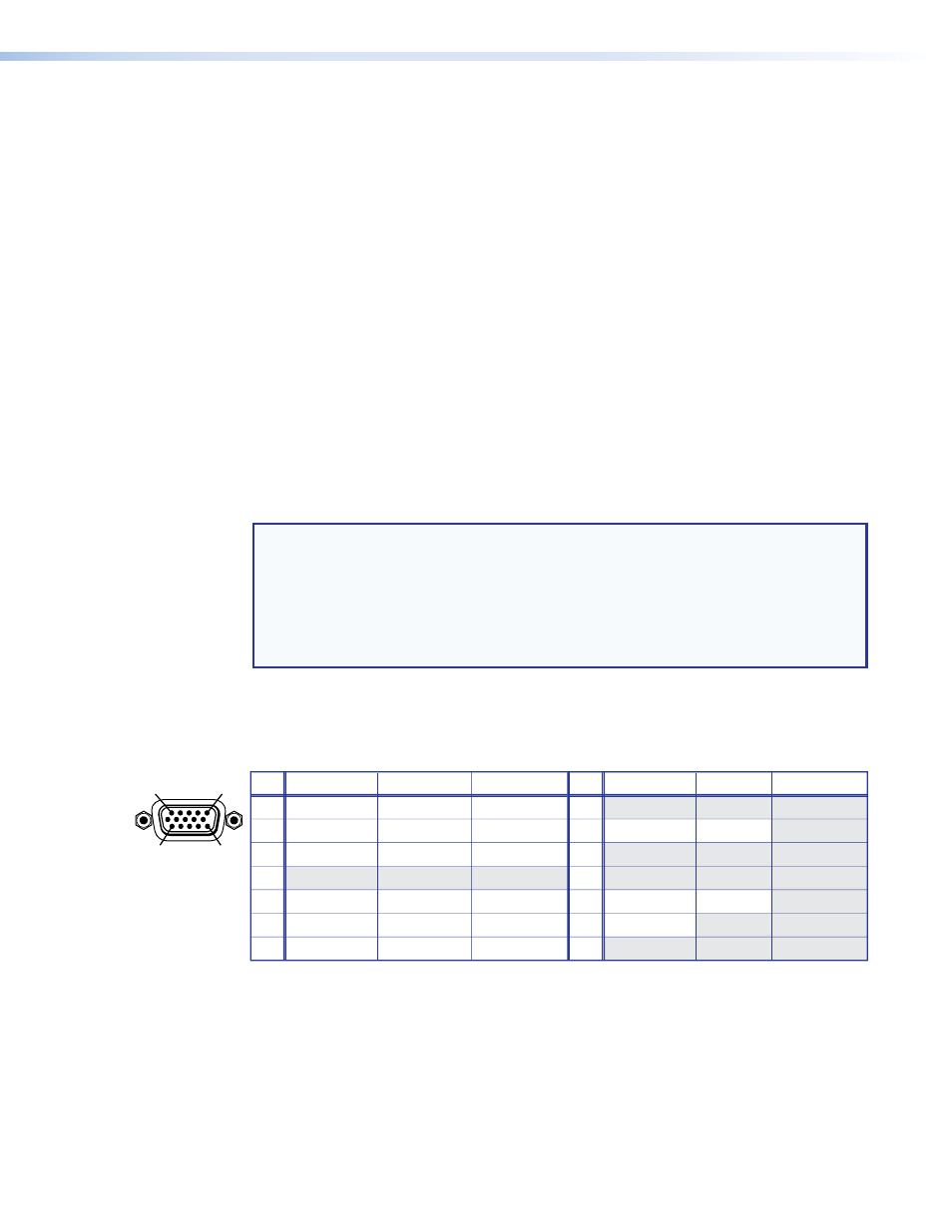
VGA connector wiring
The 15-pin HD (VGA) universal analog input ports accept RGB (RGBHV, RGBS, RGsB) and
component video. Figure 4 shows the pinouts for each format type on the connector.
Pin
RGBHV
1
Red
Green
R-Y
Y
Red return
R-Y return
Green return
Y return
Blue return
B-Y return
NC
NC
Blue
B-Y
RGBS
Component
2
Red
Green
NC
6
Red return
7
Green return
8
Blue return
3
Blue
1
5
11
15
4, 5
Pin
RGBHV
RGBS
Component
9
10
14
15
11
12
13
NC
Ground
V sync
NC
H sync
NC
Ground
NC
NC
NC
NC
C sync
NC
NC
NC
NC
NC
NC
NC
NC
NC
Figure 4.
VGA Connector