Extron Electronics Cable Cubby 1400 Connectivity Brackets User Manual
Cable pass-through bracket
Connectivity Brackets for Cable Cubby 1200 and 1400 •
Setup Guide
This guide provides instructions for assembling and installing the following accessories for
the Cable Cubby 1200 and 1400:
• Cable pass-through bracket — small
• Retractor filler bracket — small
Connectivity brackets allow users to configure the Cable Cubby enclosure with the power
module installed at the center and two cable pass-through modules on the sides (see the image
at the bottom of this page) or two retractor assemblies on the sides (see the next page).
Cable Pass-Through Bracket
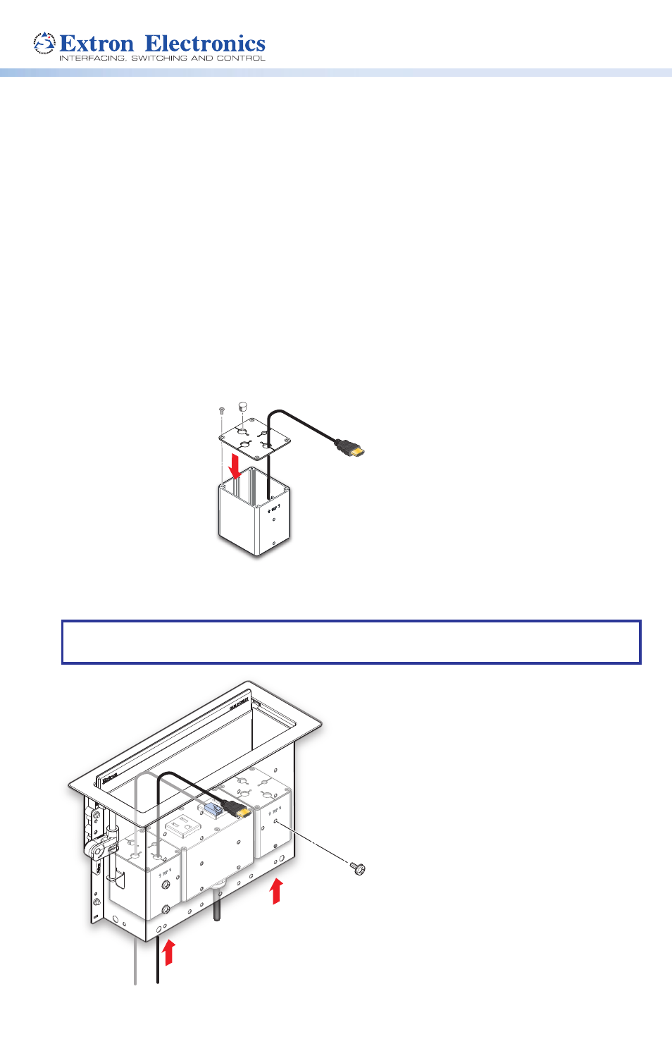
Step 1 — Assemble the cable pass-through brackets
Step 2 — Install cable pass-through brackets in the Cable Cubby
Follow the steps below to install the brackets on the left and right sides of the power module.
NOTE:
For instructions on installing the power module, see the Cable Cubby 1200 and
1400 Installation Guide.
Secure the brackets using
the provided mounting screw
with star washer (4).
Insert the brackets into
the Cable Cubby.
1
2
Insert cables through the
bottom of the connectivity
bracket and into the holes
of the grommet plate.
Secure the grommet plate
on the connectivity bracket,
using four of the provided
module screws.
Use the provided mounting screw
with the star washer to secure the
bracket in place.
Insert the mounting
pin through the
retractors.
Insert the retractor filler bracket into the
Cable Cubby enclosure as shown above.
Use the clip to secure
the mounting pin.
1
2
1
2
3
4
Snap the included hole plugs
into any unused holes.
Insert cables through the bottom of
the bracket and into the holes of the
grommet plate.
Secure the grommet
plate on the bracket,
using four of the provided
module screws.
1
2
3
3
Use the clip to secure
he mounting pin.
2
125V~ 12A MAX
TO
TAL
Insert the brackets into
the Cable Cubby.
1
2
Use the provided mounting screws with the
star washers to secure the brackets in place.