Annotator • setup guide (continued), Powering up, Front panel overview – Extron Electronics Annotator Setup Guide User Manual
Page 2: Setting the front panel locks (executive modes), Step 6 — connect control devices, Step 7 — connect power
Annotator • Setup Guide (Continued)
2
Step 6 — Connect control devices
LAN Ethernet port — Connect an Ethernet LAN or WAN via this RJ-45 connector
o
for remote control of the Annotator using a
PC’s Internet browser, or the SPPCP control program.
One Ethernet connection LED lights green when connected to the LAN and one flickers amber as the devices communicate.
RS-232 ports — For serial RS-232 or RS-422 control, connect a host computer or control system via a 9-pin D connector
p
.
RS-232 protocol (default values): 9600 baud, 1 stop bit, no parity, 8 data bits, no flow control.
Step 7 — Connect power
AC power connector — Plug in a standard IEC power cord from a 100 to 240 VAC, 50 - 60 Hz power source into this receptacle a
.
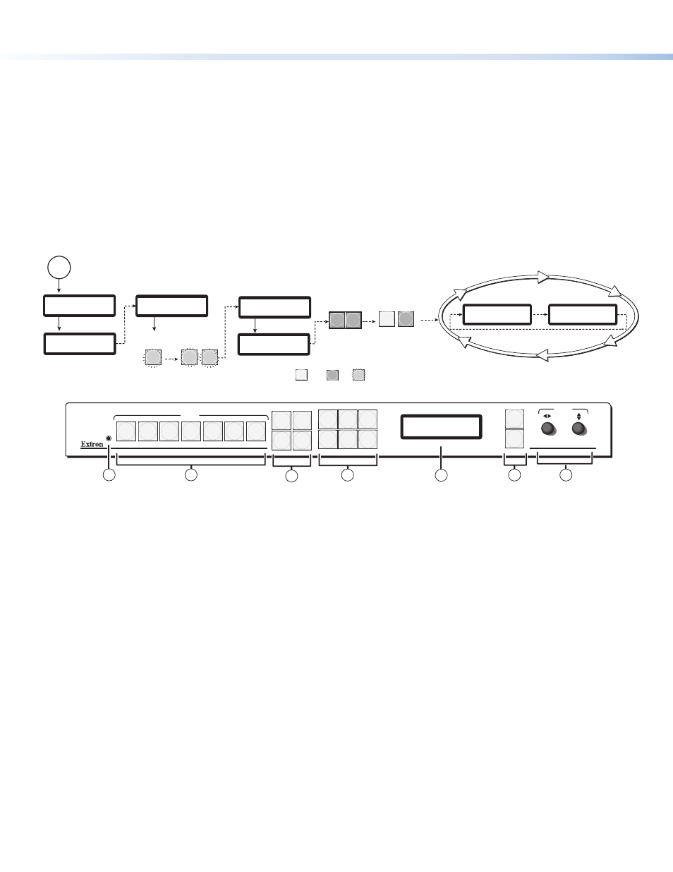
Powering Up
When powering up the Annotator, the unit undergoes a self testing sequence (see image below). The LCD displays the default
display cycle, showing the output rate and the refresh rates for the currently selected input.
When not in any menu mode the screen cycles through the input/output configuration currently installed.
3
sec.
10
sec.
Apply
Power
Extron
Annotator
v1.xx
1
sec.
2 sec.
2
sec.
Default Display Cycle
Input #2
60.0kHz 75.0Hz
1024x768 60.0Hz
Output Rate
N
The input and output rates shown in the default display
cycle may differ, depending on the type of video signal active.
Menu and Next buttons
remain lit.
All buttons flash in sequence
(green, red, amber).
MENU
NEXT
1
sec.
All input buttons
flash consecutively (amber).
2
1
1
sec.
2
1
Last active input
button remains lit.
= unlit
= lit
= flashing
Key
3
sec.
Loading OSD file
complete
Sorting graphics
files
Boot-up sequence
complete
Extron
Annotator
v1.xx
3
sec.
Front Panel Overview
ANNOTATOR
ANNOTATION GRAPHICS PROCESSOR
ADJUST
DETAIL
ZOOM
/PAN
BRIGHT
/CONT
COLOR
/TINT
SIZE
POSITION
UNDO
/CLEAR
CAPTURE
/RECALL
AUTO
IMAGE
FREEZE
6
7
5
4
3
2
1
MENU
NEXT
INPUTS
1
2
5
3
4
6
7
a
Front panel configuration port — Connect a control system or computer to this (RS-232) port, using a TRS RS-232 cable,
Extron part number 70-335-01. RS-232 protocol (default values): 9600 baud, 1 stop bit, no parity, 8 data bits, no flow control
b
Input selection buttons — Selects/switches inputs, and indicates which input is active (button lights amber).
c
Special function buttons — These four, dual colored buttons are:
• Undo/Clear — Allows a reversal of up to the last seven annotation points. Press and hold to clear annotations.
• Auto Image— Allows automatic image adjustment on selected input.
• Capture/Recall — Allows the capture and saving of the current image or the recall of a saved image.
• Freeze — Allows the current displayed image to be frozen or unfrozen as desired.
d
Picture contol buttons — These six, dual colored buttons are:
• Size — Allows adjustment to the displayed image size.
• Bright/Cont — Allows adjustment of the brightness and contrast settings for the displayed image.
• Detail — Allows adjustment of the detail (sharpness) setting for the displayed image.
• Position — Allows horizontal and/or vertical position adjustment of the displayed image.
• Color/Tint — Allows adjustment of the color and tint settings for the displayed image.
• Zoom/Pan — Allows displayed image to be zoomed in or back out, or panned horizontally and/or vertically
.
e
LCD display — This 16x2 screen displays device settings and menu configuration information.
f
Menu navigation buttons (Menu, Next) — These buttons allow navigation through the Annotator's menu system.
g
Adjust knobs — These are used with the picture adjustment and the menu navigation buttons to adjust settings.
Setting the Front Panel Locks (Executive Modes)
The Annotator has three modes of front panel security lock that limit the operation of the unit from the front panel.
Executive mode 0 (disabled) — The front panel is fully unlocked. This is the default setting.
Executive mode 1 (enabled) — The front panel is locked except for input switching, video freeze, and auto image.
Executive mode 2 (enabled) — The front panel is completely locked and can only be enabled and disabled using SIS commands.
See the online Annotator User Guide for SIS commands.